
Page 878 - The Mechatronics Handbook
P. 878
0066-frame-C29 Page 8 Wednesday, January 9, 2002 7:23 PM
Since the frequency response of a system is the ratio of the Fourier transforms of the output over the
input, a mapping between a continuous-time system, H(ω), and a corresponding discrete-time system,
H d (Ω), can be derived from the previous mapping as
H w() = H d Ω()| Ω=w T for −p ≤ Ω ≤ p
This mapping is useful for the design of both digital filters and digital controllers.
29.4 Digital Filter Design
The frequency response function of a discrete-time system describes how the system processes input
signals of different frequencies. Consider an input signal x[n] = A cos(Ω 0 n) to a system with frequency
response H(Ω) where 0 ≤ Ω 0 ≤ 2π. The corresponding output is given by
(
(
yn[] = |H Ω 0 )|cos ( Ω 0 n + ∠H Ω 0 ))
For aperiodic signals, the filtering property of Fourier transforms gives the relationship:
Y Ω() = H Ω()X Ω()
Thus, if H Ω() is small over a certain range of frequencies, then input signals with frequency content
in that range are attenuated as they pass through the system.
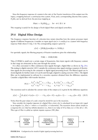
It is often convenient to filter continuous-time signals through a digital filter as shown in Fig. 29.4.
The analog-to-digital converter (ADC) samples the continuous-time signal creating a sequence of discrete-
time signals for processing by the computer or digital signal processing board. The filtered signal can be
stored digitally for further study or it can be sent through a digital-to-analog converter (DAC). The digital
filter can be implemented in software by a recursive equation obtained from the difference equation.
Consider a digital filter with transfer function:
b 1 z + b 2 z N−1 + … + b 1 + b 2 z + … + b N+1 z −N
N
−1
Hz() = ------------------------------------------------------------ = -----------------------------------------------------------
b N+1
a 1 z + a 2 z N−1 + … + a N+1 a 1 + a 2 z + … + a N+1 z −N
N
−1
The recursion used to calculate the current value of the output y[n] is given by the difference equation:
1
[
yn[] = ---- b 1 xn[] +( b 2 xn 1] + … + b N+1 xn N] a 2 yn 1] – … – a N+1 yn N]) (29.5)
[
[
[
–
–
–
–
–
a 1
Notice that the past values of y and x must be stored for use in the recursion.
Now consider the impulse response of a digital filter, where y[n] is calculated for an input x[n] equal
to an impulse (i.e., δ[n] = 1 when n = 0 and δ[n] = 0 otherwise). The recursion shown above results in
a response for y[n] that has infinite duration (i.e., there is no value of M so that y[n] = 0 for all n > M).
This type of filter is called an infinite impulse response (IIR) filter.
Analog to Computer or Digital to
Digital Digital Signal Analog
Converter Processing (DSP) Converter
(ADC) Board (DAC)
FIGURE 29.4 Configuration for standard digital signal processing hardware.
©2002 CRC Press LLC