Page 913 - The Mechatronics Handbook
P. 913
0066_Frame_C30  Page 24  Thursday, January 10, 2002  4:44 PM


                       offers an infinite upward gain margin and a downward gain margin of 1/6 (−15.56 dB). The resulting
                       unity gain crossover frequency is w g  = 35  = 5.92 rad/s and the associated phase margin is about 99.59°.
                       Not bad.
                         The following example extends the LQG/LTR ideas presented in Example 30.3 to the general MIMO
                                                                                          2
                       setting—enabling the design of feedback loops (with nominal robustness margins) via H  optimization.

                       Example 30.4 (MIMO LQG and LQG/LTR Control Design Via HH  2  Optimization)
                       We consider a MIMO plant P defined by the state space representation

                                                         x ˙ =  Ax +  Bu                       (30.139)

                                                         y =  Cx                               (30.140)

                       It is assumed that the plant P = [A, B, C] is stabilizable and detectable.
                                                     2
                         The goal is to demonstrate how the H  optimal output feedback solution that has been presented may
                       be used to solve MIMO LQG control problems. We specifically would like to present a method which
                       lends itself to the concept of LTR—whereby we use a model-based LQG controller to recover a target
                       loop transfer function matrix with desirable closed loop properties. Our motivation is not optimal
                       stochastic LQG control problems; it is the design of control laws with desirable closed loop properties.
                         Construction of Generalized Plant G. With our final objective being a model-based compensator defined
                       by a control gain matrix G c  and a filter gain matrix H f , we consider the following generalized plant:

                                                       x ˙ =  Ax + Lξ +  Bu                    (30.141)

                                                              Mx
                                                       z =  ---------------------              (30.142)
                                                             rI n × n
                                                                u  u
                                                       y =  Cx +  µq                           (30.143)


                       where u is the control, x is the (generalized) plant state, w 1  = ξ represents process noise in the state
                                                                                                  n×n
                                                                                         n×n
                       equation, w 2  = q represents sensor noise in the measurement equation, A ∈R  n×n , L ∈  R  u , B ∈  R  u  ,
                       M ∈ R n ×n , C ∈ R n ×n , n y  = n u , r > 0, µ > 0.
                                     y
                             y
                         Design Parameter Assumptions. It is assumed that either:
                         (A, L) has no imaginary uncontrollable modes and (A, M) is detectable, or
                         (A, L) is stabilizable and (A, M) has no imaginary unobservable modes.
                       Here, L, M, m, and r should be viewed as “design parameters” that are selected in order to obtain control
                       and filter gain matrices G, and H f  such that the resulting model-based compensator exhibits desirable
                       closed loop properties.
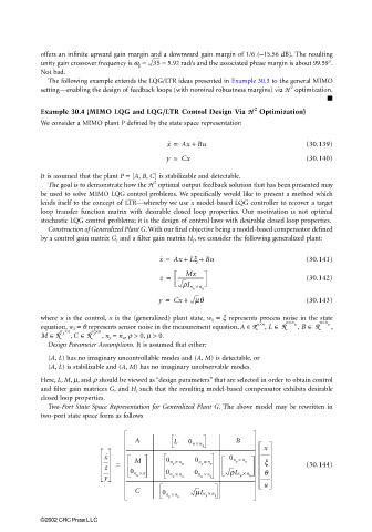
                         Two-Port State Space Representation for Generalized Plant G. The above model may be rewritten in
                       two-port state space form as follows


                                                A          L   0 n ×        B
                                                                  n
                                                                  y
                                                                                   x
                                        x ˙                               0 n ×  n
                                           =    M        0 n ×  n u  0 n ×  n y  y  u  x       (30.144)
                                                                  y
                                                          y
                                        z
                                               0 n ×  n  0 n ×  n  0 n × n  rIn ×  n  q
                                        y        u        u  u    u  y       u  u
                                                                                   u
                                                C       0 n ×    mIn × n
                                                         y  n  u   y  y
                       ©2002 CRC Press LLC

