
Page 343 - Thermal Hydraulics Aspects of Liquid Metal Cooled Nuclear Reactors
P. 343
312 Thermal Hydraulics Aspects of Liquid Metal Cooled Nuclear Reactors
Assembly
duct
Fuel rod
and wire
W H
Interior
subchannel P Corner
subchannel
Edge
subchannel
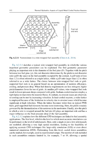
Fig. 6.2.3.1 Nomenclature in a wire-wrapped fuel assembly (Chen et al., 2014).
Fig. 6.2.3.1 sketches a typical wire-wrapped fuel assembly in which the various
important geometric parameters can be explained. The first geometric parameter
playing an important role is the diameter of the fuel pins (D). Together with the pitch
between two fuel pins (p), this rod diameter determines by the pitch-to-rod diameter
ratio (p/D) the space in the fuel assembly occupied by the coolant. A p/D ratio of less
than 1.2 is often referred to as a tight lattice, while a p/D ratio larger than 1.2 is often
referred to as a wide lattice. The choice between wire-wrapped fuel rods or grid-
supported fuel rods is in general based on an optimization of neutron efficiency,
cooling, and pressure drop. When fuel density requirements are less stringent, higher
pitch/diameters favor the use of grids. At smaller p/D values, wire-wrapped fuel rods
result in lower pressure drops compared with grids. Sodium-cooled reactors employ a
tight lattice to maximize the neutron fluxes. In sodium, no erosion issues are observed,
so cooling can be met by increasing velocities. In lead-cooled reactors, a wider lattice
is employed because of the limitation in velocity due to erosion issues which become
significant at high velocities. When the lattice becomes wider than in typical PWR
fuels, grid-supported fuel elements become more interesting. Here, the pitch is mainly
governed by the thermalization of the neutrons in the moderator. Finally, also the pitch
in which a wire is wrapped around the fuel pin (H) plays an important role and has a
major influence on the final pressure drop of the fuel assembly.
Fig. 6.2.3.2 explains how the different CFD techniques are linked to fuel assembly
applications. The first level, which is the level to which most accurate simulations can
be performed, is the level of subchannels. Here, only a single or just a few subchannels
are modeled, allowing a very high spatial resolution, leading to the feasibility of
applying accurate CFD techniques like large-eddy simulation (LES) or even direct
numerical simulation (DNS). Elaborating from this level, scaled down assemblies
can be studied, for example, used in experimental setups. The number of rods included
in such assemblies remains limited to, for example, 7 or 19, allowing a spatial