
Page 126 - Introduction to Marine Engineering
P. 126
Pumps and pumping systems 113
Suction 1
-J
tank |
DtS
TANK
PRESS
SUCT
ATM
|
Suction -U
io
n
tank j
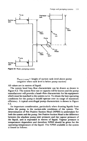
Figure 6.1 Basic pumping system
HsucrrTANK = height of suction tank level above pump
(negative when tank level is below pump suction)
All values are in metres of liquid.
The system head loss—flow characteristic can be drawn as shown in
Figure 6.2. The system flow rate or capacity will be known and the pump
manufacturer will provide a head—flow characteristic for his equipment
which must be matched to the system curve. To obtain the best operating
conditions for the pump it should operate over its range of maximum
efficiency. A typical centrifugal pump characteristic is shown in Figure
6.2.
An important consideration, particularly when drawing liquids from
below the pump, is the suction-side conditions of the system. The
determination of Net Positive Suction Head (NPSH) is undertaken for
both the system and the pump. Net Positive Suction Head is the difference
between the absolute pump inlet pressure and the vapour pressure of
the liquid, and is expressed in metres of liquid. Vapour pressure is
temperature dependent and therefore NPSH should be given for the
operating temperature of the liquid. The NPSH available in the system
is found as follows: