
Page 133 - Introduction to Marine Engineering
P. 133
Pumps and pumping systems 119
is equivalent to a low lift centrifugal pump and the higher speeds
possible enable a smaller driving motor to be used. The axial-flow pump
is also suitable for supplementary use in a condenser scoop circulating
system since the pump will offer little resistance to flow when idling.
With scoop circulation the normal movement of the ship will draw in
water; the pump would be in use only when the ship was moving slowly
or stopped.
Centrifugal pump
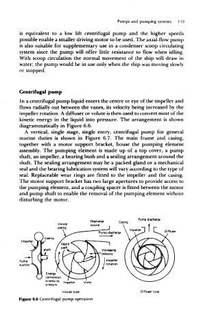
In a centrifugal pump liquid enters the centre or eye of the impeller and
flows radially out between the vanes, its velocity being increased by the
impeller rotation. A diffuser or volute is then used to convert most of the
kinetic energy in the liquid into pressure. The arrangement is shown
diagrammatically in Figure 6.6.
A vertical, single stage, single entry, centrifugal pump for general
marine duties is shown in Figure 6.7. The main frame and casing,
together with a motor support bracket, house the pumping element
assembly. The pumping element is made up of a top cover, a pump
shaft, an impeller, a bearing bush and a sealing arrangement around the
shaft. The sealing arrangement may be a packed gland or a mechanical
seal and the bearing lubrication system will vary according to the type of
seal. Replaceable wear rings are fitted to the impeller and the casing.
The motor support bracket has two large apertures to provide access to
the pumping element, and a coupling spacer is fitted between the motor
and pump shaft to enable the removal of the pumping element without
disturbing the motor.
Pump discharge
Volute
casing
Diffuser
Casing
impeller
shaft increasing
velocity
I Impeller
/ rotation
Energy
conversion
kinetic to |mpe)|er v ), ne
pressure
Volute type Oiffuser type
Figure 6.6 Centrifugal pump operation