
Page 73 - Introduction to Marine Engineering
P. 73
60 Steam turbines and gearing
One method of achieving this balance is the use of a dummy piston
and cylinder. A pipe from some stage in the turbine provides steam to
act on the dummy piston which is mounted on the turbine rotor (Figure
3.7). The rotor casing provides the cylinder to enable the steam pressure
to create an axial force on the turbine shaft. The dummy piston annular
area and the steam pressure are chosen to produce a force which exactly
balances the end thrust from the reaction blading. A turbine with ahead
and astern blading will have a dummy piston at either end to ensure
balance in either direction of rotation.
Another method often used in low-pressure turbines is to make the
turbine double flow. With this arrangement steam enters at the centre of
the shaft and flows along in opposite directions. With an equal division
of steam the two reaction effects balance and cancel one another.
Glands and gland sealing
Steam is prevented from leaking out of the rotor high-pressure end and
air is prevented from entering the low-pressure end by the use of glands.
A combination of mechanical glands and a gland sealing system is usual.
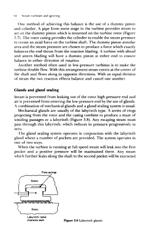
Mechanical glands are usually of the labyrinth type. A series of rings
projecting from the rotor and the casing combine to produce a maze of
winding passages or a labyrinth (Figure 3.8). Any escaping steam must
pass through this labyrinth, which reduces its pressure progressively to
zero.
The gland sealing system operates in conjunction with the labyrinth
gland where a number of pockets are provided. The system operates in
one of two ways.
When the turbine is running at full speed steam will leak into the first
pocket and a positive pressure will be maintained there. Any steam
which further leaks along the shaft to the second pocket will be extracted
Plate springs
Labyrinth radial
clearance seals Figure 3.8 Labyrinth glands