
Page 172 - Materials Chemistry, Second Edition
P. 172
9 Life Cycle Inventory Analysis 157
System boundaries
UP4 UP5
Background system
Foreground system
UP1 UPa
UPd
UP2 UPb UPf
UPe
UP3 UPc
UP6 UP7 UP8
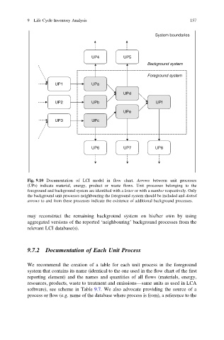
Fig. 9.10 Documentation of LCI model in flow chart. Arrows between unit processes
(UPs) indicate material, energy, product or waste flows. Unit processes belonging to the
foreground and background system are identified with a letter or with a number respectively. Only
the background unit processes neighbouring the foreground system should be included and dotted
arrows to and from these processes indicate the existence of additional background processes.
may reconstruct the remaining background system on his/her own by using
aggregated versions of the reported ‘neighbouring’ background processes from the
relevant LCI database(s).
9.7.2 Documentation of Each Unit Process
We recommend the creation of a table for each unit process in the foreground
system that contains its name (identical to the one used in the flow chart of the first
reporting element) and the names and quantities of all flows (materials, energy,
resources, products, waste to treatment and emissions—same units as used in LCA
software), see scheme in Table 9.7. We also advocate providing the source of a
process or flow (e.g. name of the database where process is from), a reference to the