
Page 345 - Moving the Earth_ The Workbook of Excavation
P. 345
ROADWAYS
ROADWAYS 8.7
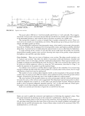
FIGURE 8.3 Typical cross section.
The usual scale is 100 feet to 1 inch horizontally and 10 feet to 1 inch vertically. The exaggera-
tion of the vertical scale is necessary because the ups and downs are usually quite small compared
to the horizontal distances, and would be hard to measure accurately on a small scale.
The road profile is made of a series of straight lines or grades connected by curves. These ver-
tical curves are usually arcs of parabolas, not circles. Plus grades go up as they go away from zero
station, and minus grades go down.
The ground profile is prepared from topographic maps, often made by stereoscopic photography
from the air. Profiles may be prepared for several possible routes, and highway profiles sketched
along them. A ground survey is made along the selected route to serve as the basis for final plans.
A rough estimate of the volume of cuts and fills can be made from the profile, but accurate
determination usually requires cross sections showing side slope of the ground, slopes proposed
for highway cuts and fills, and other details.
Cross Sections. There are two types of highway cross section. The plans usually include a set
of “typical road sections” that show the details of pavement width and thickness, shoulder and
gutter width, crown or side slope, and other construction information. These typical sections serve
as guides in staking out and building the road. See Fig. 8.3. The cross section for the roadway can
be achieved without numerous stakes by using the TS5 instruments, described in Chap. 2, to
enable the operator on the grader to get the required shape.
An ordinary cross section is a profile taken at right angles to the centerline. It is at least long
enough to include the full width that will be graded. It is usually taken with a transit, but for rough
calculations a hand level may be satisfactory.
The number of cross sections taken depends chiefly on the irregularity of the ground. In hilly
country they are taken at each 100-foot station, and at additional points where the ground surface
changes. On perfectly flat land only one or two might be taken on a whole project.
The cross section of the ground is drawn on cross-section paper with the vertical and horizon-
tal scales the same, or the vertical scale exaggerated. Then the proper typical road section is select-
ed and its subgrade line is drawn in, on the same scale and in proper location. Wherever present
grade is above proposed subgrade, material must be “cut” or dug and removed. Where pres-
ent grade is lower than subgrade, material must be added or filled in.
Such cross sections provide data to figure the cut and fill for the road.
STAKES
Stakes are used to guide the contractor and employees in following the engineer’s plans. They
also assist inspectors in checking up on the contractor’s performance. (See Fig. 8.4.)
The first working stakes on the job may be the centerline, showing depth of cut and height of
fill, and slope stakes that show the outer limits of the area to be cleared, grubbed, and graded, and
usually the cut and fill information also. Some of these stakes would not be necessary if the TS5,
mentioned above, is to be used.