
Page 449 - Moving the Earth_ The Workbook of Excavation
P. 449
BLASTING AND TUNNELING
BLASTING AND TUNNELING 9.49
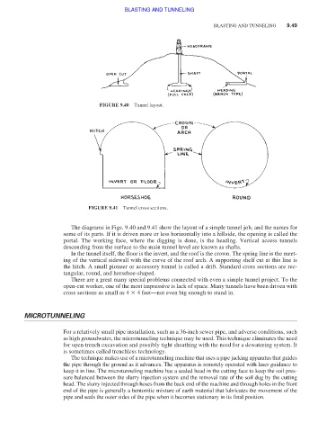
FIGURE 9.40 Tunnel layout.
FIGURE 9.41 Tunnel cross sections.
The diagrams in Figs. 9.40 and 9.41 show the layout of a simple tunnel job, and the names for
some of its parts. If it is driven more or less horizontally into a hillside, the opening is called the
portal. The working face, where the digging is done, is the heading. Vertical access tunnels
descending from the surface to the main tunnel level are known as shafts.
In the tunnel itself, the floor is the invert, and the roof is the crown. The spring line is the meet-
ing of the vertical sidewall with the curve of the roof arch. A supporting shelf cut at this line is
the hitch. A small pioneer or accessory tunnel is called a drift. Standard cross sections are rec-
tangular, round, and horsehoe-shaped.
There are a great many special problems connected with even a simple tunnel project. To the
open-cut worker, one of the most impressive is lack of space. Many tunnels have been driven with
cross sections as small as 4 4 feet—not even big enough to stand in.
MICROTUNNELING
For a relatively small pipe installation, such as a 36-inch sewer pipe, and adverse conditions, such
as high groundwater, the microtunneling technique may be used. This technique eliminates the need
for open trench excavation and possibly tight sheathing with the need for a dewatering system. It
is sometimes called trenchless technology.
The technique makes use of a microtunneling machine that uses a pipe jacking apparatus that guides
the pipe through the ground as it advances. The apparatus is remotely operated with laser guidance to
keep it in line. The microtunneling machine has a sealed head in the cutting face to keep the soil pres-
sure balanced between the slurry injection system and the removal rate of the soil dug by the cutting
head. The slurry injected through hoses from the back end of the machine and through holes in the front
end of the pipe is generally a bentonitic mixture of earth material that lubricates the movement of the
pipe and seals the outer sides of the pipe when it becomes stationary in its final position.