
Page 154 - Materials Chemistry, Second Edition
P. 154
Mass-Balance Concept and Reactor Design 137
Q, C 0 Q, C 1 Q, C 2 Q, C 3
V 1 V 2 V 3
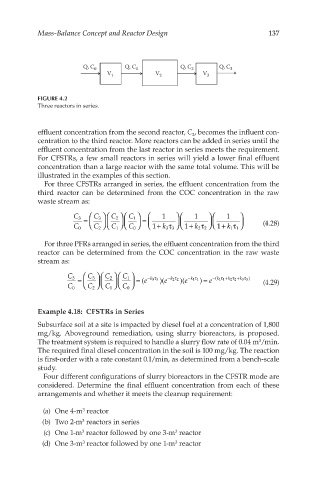
FIGURE 4.2
Three reactors in series.
effluent concentration from the second reactor, C , becomes the influent con-
2
centration to the third reactor. More reactors can be added in series until the
effluent concentration from the last reactor in series meets the requirement.
For CFSTRs, a few small reactors in series will yield a lower final effluent
concentration than a large reactor with the same total volume. This will be
illustrated in the examples of this section.
For three CFSTRs arranged in series, the effluent concentration from the
third reactor can be determined from the COC concentration in the raw
waste stream as:
C 3 C 2 C 1 1 1 1
C 3
= = (4.28)
C 0 C 2 C 1 C 0 1+ k 3 3 τ 1+ k 2 2 τ 1+ k 1 1 τ
For three PFRs arranged in series, the effluent concentration from the third
reactor can be determined from the COC concentration in the raw waste
stream as:
C 3 C 2 C 1
C 3 − k 33 τ − k 22 τ −τ − k ( 11 τ + k 22 τ + k 33 τ )
= = e ( )( e )( e k 11 ) = e (4.29)
C 0 C 2 C 1 C 0
Example 4.18: CFSTRs in Series
Subsurface soil at a site is impacted by diesel fuel at a concentration of 1,800
mg/kg. Aboveground remediation, using slurry bioreactors, is proposed.
The treatment system is required to handle a slurry flow rate of 0.04 m /min.
3
The required final diesel concentration in the soil is 100 mg/kg. The reaction
is first-order with a rate constant 0.1/min, as determined from a bench-scale
study.
Four different configurations of slurry bioreactors in the CFSTR mode are
considered. Determine the final effluent concentration from each of these
arrangements and whether it meets the cleanup requirement:
(a) One 4-m reactor
3
(b) Two 2-m reactors in series
3
(c) One 1-m reactor followed by one 3-m reactor
3
3
(d) One 3-m reactor followed by one 1-m reactor
3
3