
Page 161 - Materials Chemistry, Second Edition
P. 161
144 Practical Design Calculations for Groundwater and Soil Remediation
Q , C 0 V Q , C 1
1
1
Q, C 0 1 Q, C f
Q , C 0 Q , C 2
2
2
V 2
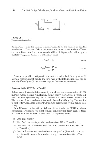
FIGURE 4.3
Two reactors in parallel.
different; however, the influent concentrations to all the reactors in parallel
are the same. The sizes of the reactors may not be the same, and the effluent
concentrations from the reactors can be different (Figure 4.3). In that figure,
the following mass-balance equations are valid:
=
QQ 1 + (4.30)
Q 2
QC 1 + QC 2
C f = 1 2 (4.31)
Q 1 + Q 2
Reactors in parallel configurations are often used in the following cases: (1)
a single reactor cannot handle the flow rate; (2) the total influent rate fluctu-
ates significantly; or (3) the reactors require frequent maintenance.
Example 4.22: CFSTRs in Parallel
Subsurface soil at a site is impacted by diesel fuel at a concentration of 1,800
mg/kg. Aboveground remediation, using slurry bioreactors, is proposed.
The treatment system is required to handle a slurry flow rate of 0.04 m /min.
3
The required final diesel concentration in the soil is 100 mg/kg. The reaction
is first-order with a rate constant 0.1/min, as determined from a bench-scale
study.
Four different configurations of slurry bioreactors in the CFSTR mode are
considered. Determine the final effluent concentration from each of these
arrangements and whether it meets the cleanup requirement:
3
(a) One 4-m reactor
3
(b) Two 2-m reactors in parallel (each receives 0.02 m /min flow)
3
3
(c) One 1-m reactor and one 3-m reactor in parallel (each receives 0.02
3
m /min flow)
3
3
(d) One 1-m reactor and one 3-m reactor in parallel (the smaller reactor
3
3
3
receives 0.01 m /min flow while the larger one receives 0.03 m /min
flow)