
Page 276 -
P. 276
OXIDATION AND DISINFECTION 10.21
DR£S5~£ RELIEF VALVE
(R(LIEVES AT I0" TO ZO"
DIFJCEREN TJAL REGU~AI"ING
LEGEND
I--'~GAS
V~LAYd GAUGE 'Tr
~WATER
t/3 ° ro 40"
~SOLuT~O~
CHLORINE GAS
FEED,ER
n----
STANDARO
v~CuUe
SOLUTION
~EGULATO~ L DISCHARGE
CH~CK UNIT
INaCCTOFt
GAS
~
REMOTE FROM
CONTROL MODULE
AuTO~AT~
• SWlTCHOVER
~VECTOR
i , CM~C~ UN,V •
war£R SUPPLY
i ~ I~:SEO r~ PAmSJ O~N RELIEF"
SUP~L~
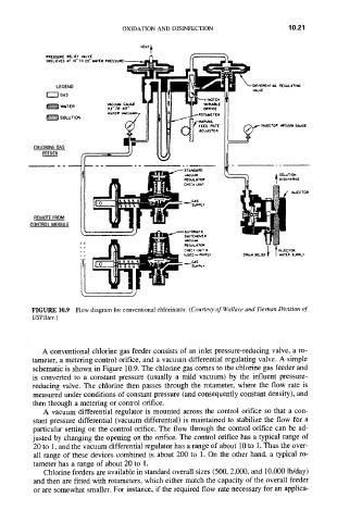
FIGURE 10.9 Flow diagram for conventional chlorinator. (Courtesy of Wallace and Tiernan Division of
USFilter.)
A conventional chlorine gas feeder consists of an inlet pressure-reducing valve, a ro-
tameter, a metering control orifice, and a vacuum differential regulating valve. A simple
schematic is shown in Figure 10.9. The chlorine gas comes to the chlorine gas feeder and
is converted to a constant pressure (usually a mild vacuum) by the influent pressure-
reducing valve. The chlorine then passes through the rotameter, where the flow rate is
measured under conditions of constant pressure (and consequently constant density), and
then through a metering or control orifice.
A vacuum differential regulator is mounted across the control orifice so that a con-
stant pressure differential (vacuum differential) is maintained to stabilize the flow for a
particular setting on the control orifice. The flow through the control orifice can be ad-
justed by changing the opening on the orifice. The control orifice has a typical range of
20 to 1, and the vacuum differential regulator has a range of about 10 to 1. Thus the over-
all range of these devices combined is about 200 to 1. On the other hand, a typical ro-
tameter has a range of about 20 to 1.
Chlorine feeders are available in standard overall sizes (500, 2,000, and 10,000 lb/day)
and then are fitted with rotameters, which either match the capacity of the overall feeder
or are somewhat smaller. For instance, if the required flow rate necessary for an applica-