
Page 89 -
P. 89
AERATION AND AIR STRIPPING 5.5
Diffuser Aerators. The most common type of equipment for diffusion aeration consists
of rectangular concrete tanks in which perforated pipes, porous diffuser tubes or plates,
or other impingement devices are inserted. Compressed air is injected through the system
to produce fine bubbles, which, on rising through the water, produce turbulence resulting
in effective water-air mixing.
This type of aeration technique is often adapted to existing storage tanks and basins.
If porous tubes or perforated pipes are used, they may be suspended at about one-half
tank depth to reduce compression head. Porous plates are usually located on the bottom
of the tank. Static tube aerators are also used in a variety of applications and provide ad-
equate aeration when properly designed.
A relatively new type of diffused aeration equipment is the low-profile system, which
is a multistage, diffused bubble air stripping device. The device differs from conventional
systems in that it operates with a water depth of about 18 to 36 in. (46 to 92 cm) com-
pared with 10 ft (3 m) or greater for conventional installations. Shallow water depth per-
mits the use of regenerative or centrifugal blowers instead of compressors and reduces
overall height of the device to less than 4 to 5 ft.
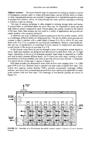
In this system, water flows by gravity through a series of completely mixed staged re-
actors. Individual modules are designed and fabricated to include three, four, six, or eight
stages, depending on the level of treatment required. Each stage is separated by a baffle
wall and includes separate diffuser heads. Air is blown into each stage, creating a turbu-
lent mixture of diffused bubbles and water to provide efficient mass transfer. A schematic
of a typical device of this type is shown in Figure 5.3.
Individual modules are designed to treat water at flow rates ranging from 1 to 1,000
gpm (0.06 to 63 L/s). Modules used in parallel can treat water at higher flow rates. This
system also removes carbon dioxide, VOCs, gasoline components, hydrogen sulfide,
methane, and radon from contaminated groundwater and is particularly applicable to small
water systems with low flow rates. Two drawings of low-profile systems are shown in
Figure 5.4.
II II II
I
AIR FROM
BLOWER,.~ i
INLET
~z" o° o. * T: 0 o0 o 0 o
I* o
oo :o.~
° ~o~
28: ,
)0 C )0
c~o~
O:o o d~- o3
o~ -~,c c ,°~
o,
~ o, oo oo 0 ° C oo
:: "5: oo C
~. °°
;N ~q ~q,~
TREATED o°0: C
,'?~o
o°o
0°?;,o, "o: o* o'?:~ o~
WATER
0(30I-.' O0 0 , 0~) C )o
°°° ~;~ oo0
~ ~C,o~ :;OoO ~*, C 2:
'd
ooO~:~
]
N
FIGURE 5.3 Schematic of a flow-through low-profile aeration system. (Courtesy of Lowry Aeration
Systems.)