
Page 132 - 15 Dangerously Mad Projects for the Evil Genius
P. 132
Chapter 9 ■ Covert Radio Bug 111
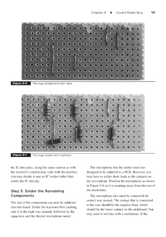
Figure 9-6 The bug stripboard with links
Figure 9-7 The bug board with resistors
the IC into place, using the same caution as with The microphone that the author used was
the receiver’s construction. Like with the receiver, designed to be soldered to a PCB. However, you
you may decide to use an IC socket rather than may have to solder short leads to the contacts on
solder the IC directly. the microphone. Position the microphone as shown
in Figure 9-8 so it is pointing away from the rest of
Step 5. Solder the Remaining the electronics.
Components The microphone also must be connected the
correct way around. The contact that is connected
The rest of the components can now be soldered
to the case should be the negative lead, which
onto the board. Solder the transistor first (making
should be the lower contact on the stripboard. You
sure it is the right way around), followed by the
may need to test this with a multimeter. If the
capacitors and the electret microphone insert.