
Page 116 - A Comprehensive Guide to Solar Energy Systems
P. 116
114 A COMPrEHEnSIvE GUIdE TO SOlAr EnErGy SySTEMS
The largest barrier is that property developers and building owners have little incentive
to invest in energy-saving equipment in new constructions and for rental market. This is
because the returns on investments flow directly to the occupants rather than to the build-
ing owners or the developers [7]. Another barrier existing in collective dwellings or multi-
story buildings is that the installation of a single device may become technically complex
and would require permits from a majority of co-owners [7]. The diversity of local require-
ments is another barrier as solar systems need to be considered in terms of their compat-
ibility with existing community aesthetic standards and architectural requirements [7,10].
Finally, some barriers relate to human behavior. These include the reluctance to manage a
complex system, the intermittence solar energy for water heating, leading to low comfort
levels, and a change in habits [7].
6.2 Working Principle of SWH Systems
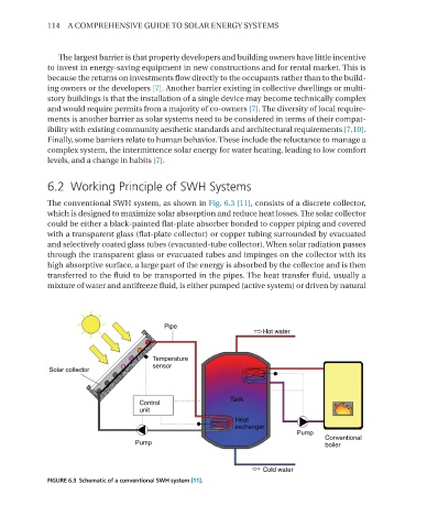
The conventional SWH system, as shown in Fig. 6.3 [11], consists of a discrete collector,
which is designed to maximize solar absorption and reduce heat losses. The solar collector
could be either a black-painted flat-plate absorber bonded to copper piping and covered
with a transparent glass (flat-plate collector) or copper tubing surrounded by evacuated
and selectively coated glass tubes (evacuated-tube collector). When solar radiation passes
through the transparent glass or evacuated tubes and impinges on the collector with its
high absorptive surface, a large part of the energy is absorbed by the collector and is then
transferred to the fluid to be transported in the pipes. The heat transfer fluid, usually a
mixture of water and antifreeze fluid, is either pumped (active system) or driven by natural
FIGURE 6.3 Schematic of a conventional SWH system [11].