
Page 15 - A Practical Introduction to Optical Mineralogy
P. 15
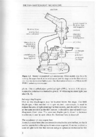
THE  TRANSMITTED-LIGHT MICROSCOPE
                                        eyepiece


 head securing
                                                          turret mount for
                                                          Bertrand lens
                                                          and magnifier
                      Bertrand lens -------~~~~;,_~b.-- analyser
                        slot for  first  _______  _,-
                     order red plate                      objective
                                                   + -- assembly
                                                          locking piece
                    thin section is
                     attached to
                   stage by  metal  - lt------"----------1---,
                         cl ips                  "":~iD'i'i'i'1'i!!iip- stage
                                                           diaphragm
                                                   -:.:;)---- lever
                   coaxial coarse             1..-t=T"'--o~---- polariscr
                       and fine
                    focusing lever     1 -~~!1--t _______ condcnser
                                       1-                  focusing


                  Figure 1.2  Modern  transmitted  light microscope. Older models may  focus  by
                  moving the upper barrel of the microscope (not the stage as in  the illustration),
                  and may use an external light source. The illustration is based on a Nikon model
 on/off switch    POH-2 polarising microscope.
 (intensity
 control)
                  plane.  This  is  called plane polarised light  (PPL).  In  most  UK  micro-
                  scopes the polariser is oriented to give E-W vibrating incident light (see
 Model MP 3502M   also  Ch. 4).
 *Analyser
 The analyser is located on the   Substage diaphragms
 left-hand side of the head mounting   One  or  two  diaphragms  may  be  located  below  the  stage.  The  field
 block on all  MP3.500 microscope
 models           diaphragm,  often  omitted  on  simple  student  microscopes,  is  used  to
                  reduce the area of light entering the thin section, and should be in focus
                  at the same position as the thin section ; it should be opened until it just
                  disappears  from  view.  The  aperture  diaphragm  is  closed  to  increase
                  resolution; it can be seen when the Bertrand lens  is  inserted.
 Figure 1.1  The Swift Student polarising microscope (photo courtesy  of Swift
 Ltd).            The  condenser or convergent lens
                  A small circular lens (the condenser) is attached to a swivel bar, so that it
                  can be inserted·into the optical train when required. It serves to direct a
                  cone of light on to the thin section and give optimum resolution for the
 2                3