
Page 259 - ARM Based Microcontroller Projects Using MBED
P. 259
8.34 USING THE PWM 245
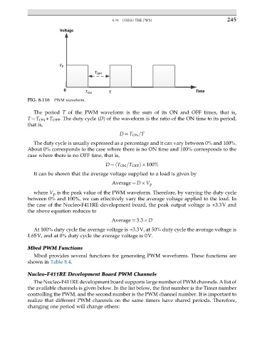
FIG. 8.116 PWM waveform.
The period T of the PWM waveform is the sum of its ON and OFF times, that is,
T¼T ON +T OFF . The duty cycle (D) of the waveform is the ratio of the ON time to its period,
that is,
D ¼ T ON =T
The duty cycle is usually expressed as a percentage and it can vary between 0% and 100%.
About 0% corresponds to the case where there is no ON time and 100% corresponds to the
case where there is no OFF time, that is,
D ¼ T ON =T OFF Þ 100%
ð
It can be shown that the average voltage supplied to a load is given by
Average ¼ D V p
where V p is the peak value of the PWM waveform. Therefore, by varying the duty cycle
between 0% and 100%, we can effectively vary the average voltage applied to the load. In
the case of the Nucleo-F411RE development board, the peak output voltage is +3.3V and
the above equation reduces to
Average ¼ 3:3 D
At 100% duty cycle the average voltage is +3.3V, at 50% duty cycle the average voltage is
1.65V, and at 0% duty cycle the average voltage is 0V.
Mbed PWM Functions
Mbed provides several functions for generating PWM waveforms. These functions are
shown in Table 8.4.
Nucleo-F411RE Development Board PWM Channels
The Nucleo-F411RE development board supports large number of PWM channels. A list of
the available channels is given below. In the list below, the first number is the Timer number
controlling the PWM, and the second number is the PWM channel number. It is important to
realize that different PWM channels on the same timers have shared periods. Therefore,
changing one period will change others: