
Page 45 - ARM Based Microcontroller Projects Using MBED
P. 45
3.4 ARM PROCESSOR-BASED MICROCONTROLLER DEVELOPMENT BOARDS 31
arm
â
CORTEX -M4
Nested vectored Wake-up interrupt
interrupt controller controller
CPU
Armv7-M
Memory protection unit DSP FPU
Data
ITM trace JTAG
watchpoint
3x
AHB-Lite
Breakpoint
ETM trace Serial wire
unit
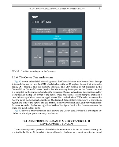
FIG. 3.2 Simplified block diagram of the Cortex core.
3.3.6 The Cortex Core Architecture
Fig. 3.2 shows a simplified block diagram of the Cortex-M4 core architecture. Near the top
left-hand side we can see the CPU which includes the ALU, register banks, instruction de-
coder, DSP module, and the memory interface. The DSP module is not available in the
Cortex-M0 or Cortex-M3 cores. Notice that the memory is not part of the Cortex core and
it is supplied by the company building the processor. The nested vectored interrupt controller
is included at the top left corner of the figure. These are external interrupt inputs that can be
used in interrupt-driven real-time applications. The core includes a FPU used to accelerate the
floating point mathematical operations. The test and debug interface is shown at the bottom
right-hand side of the figure. The bus matrix, memory protection unit, and peripheral inter-
faces are located at the bottom right hand-side of the figure. Notice that the core does not in-
clude the input-output ports.
Fig. 3.3 shows a microcontroller built around the Cortex core. Notice that this figure in-
cludes input-output ports, memory, and so on.
3.4 ARM PROCESSOR-BASED MICROCONTROLLER
DEVELOPMENT BOARDS
There are many ARM processor-based development boards. In this section we are only in-
terested in the Cortex-M-based development boards which are used in microcontroller-based