
Page 102 - Advanced Design Examples of Seismic Retrofit of Structures
P. 102
94 Advanced Design Examples of Seismic Retrofit of Structures
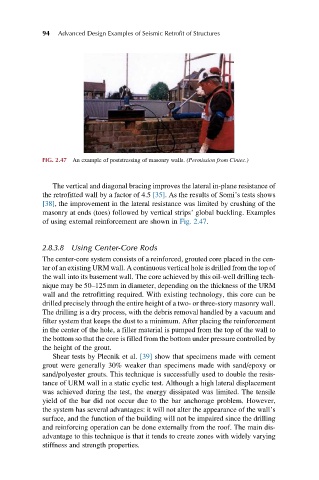
FIG. 2.47 An example of poststressing of masonry walls. (Permission from Cintec.)
The vertical and diagonal bracing improves the lateral in-plane resistance of
the retrofitted wall by a factor of 4.5 [35]. As the results of Somi’s tests shows
[38], the improvement in the lateral resistance was limited by crushing of the
masonry at ends (toes) followed by vertical strips’ global buckling. Examples
of using external reinforcement are shown in Fig. 2.47.
2.8.3.8 Using Center-Core Rods
The center-core system consists of a reinforced, grouted core placed in the cen-
ter of an existing URM wall. A continuous vertical hole is drilled from the top of
the wall into its basement wall. The core achieved by this oil-well drilling tech-
nique may be 50–125mm in diameter, depending on the thickness of the URM
wall and the retrofitting required. With existing technology, this core can be
drilled precisely through the entire height of a two- or three-story masonry wall.
The drilling is a dry process, with the debris removal handled by a vacuum and
filter system that keeps the dust to a minimum. After placing the reinforcement
in the center of the hole, a filler material is pumped from the top of the wall to
the bottom so that the core is filled from the bottom under pressure controlled by
the height of the grout.
Shear tests by Plecnik et al. [39] show that specimens made with cement
grout were generally 30% weaker than specimens made with sand/epoxy or
sand/polyester grouts. This technique is successfully used to double the resis-
tance of URM wall in a static cyclic test. Although a high lateral displacement
was achieved during the test, the energy dissipated was limited. The tensile
yield of the bar did not occur due to the bar anchorage problem. However,
the system has several advantages: it will not alter the appearance of the wall’s
surface, and the function of the building will not be impaired since the drilling
and reinforcing operation can be done externally from the roof. The main dis-
advantage to this technique is that it tends to create zones with widely varying
stiffness and strength properties.