
Page 169 - Advanced Design Examples of Seismic Retrofit of Structures
P. 169
Example of an RC Building Retrofitted by RC Shear Walls Chapter 3 161
41-13 [8], the upper-bound value of the effective length equal to the total
height of the shear wall was taken into account for walls P5 and P6.
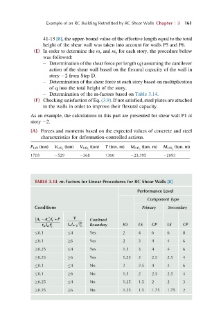
(E) In order to determine the m x and m y for each story, the procedure below
was followed:
– Determination of the shear force per length (q) assuming the cantilever
action of the shear wall based on the flexural capacity of the wall in
story 2 from Step D.
– Determination of the shear force at each story based on multiplication
of q into the total height of the story.
– Determination of the m-factors based on Table 3.14.
(F) Checking satisfaction of Eq. (3.9). If not satisfied, steel plates are attached
to the walls in order to improve their flexural capacity.
As an example, the calculations in this part are presented for shear wall P1 at
story 2.
(A) Forces and moments based on the expected values of concrete and steel
characteristics for deformation-controlled actions.
P UD (ton) V UD x (ton) V UD y (ton) T (ton. m) M UD x (ton. m) M UD y (ton. m)
1703 529 368 1300 23,395 2093
TABLE 3.14 m-Factors for Linear Procedures for RC Shear Walls [8]
Performance Level
Component Type
Conditions Primary Secondary
A s A f y + P Confined
V
0
s
p ffiffiffiffi
t w l w f c 0 t w l w f c 0 Boundary IO LS CP LS CP
0.1 4 Yes 2 4 6 6 8
0.1 6 Yes 2 3 4 4 6
0.25 4 Yes 1.5 3 4 4 6
0.25 6 Yes 1.25 2 2.5 2.5 4
0.1 4 No 2 2.5 4 4 6
0.1 6 No 1.5 2 2.5 2.5 4
0.25 4 No 1.25 1.5 2 2 3
0.25 6 No 1.25 1.5 1.75 1.75 2