
Page 176 - Advanced Design Examples of Seismic Retrofit of Structures
P. 176
168 Advanced Design Examples of Seismic Retrofit of Structures
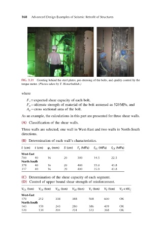
FIG. 3.31 Grouting behind the steel plates, pre-stressing of the bolts, and quality control by the
torque meter. (Photos taken by T. Honarbakhsh.)
where
F v ¼expected shear capacity of each bolt,
F u ¼ultimate strength of material of the bolt assumed as 520MPa, and
A g ¼cross sectional area of the bolt.
As an example, the calculations in this part are presented for three shear walls.
(A) Classification of the shear walls.
Three walls are selected; one wall in West-East and two walls in North-South
directions.
(B) Determination of each wall’s characteristics.
L (cm) t (cm) φ v (mm) S (cm) F y (MPa) f CL (MPa) f CE (MPa)
West-East
700 40 16 20 300 14.5 22.5
North-South
378 40 16 20 400 35.0 43.8
317 40 16 20 400 35.0 43.8
(C) Determination of the shear capacity of each segment.
(D) Control of upper bound shear strength of reinforcement.
V CL (ton) V CE (ton) V SL (ton) V SE (ton) V L (ton) V E (ton) V S <4V C
West-East
170 212 338 388 508 600 OK
North-South
143 159 243 280 386 439 OK
120 134 204 234 323 368 OK