
Page 390 - Advanced Design Examples of Seismic Retrofit of Structures
P. 390
Example of a Steel Frame Building Retrofitted Chapter 5 353
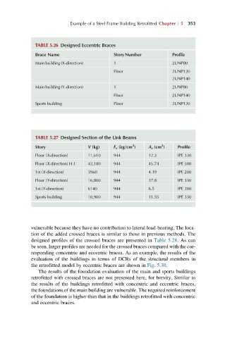
TABLE 5.26 Designed Eccentric Braces
Brace Name Story Number Profile
Main building (X-direction) 1 2UNP80
Floor 2UNP120
2UNP140
Main building (Y-direction) 1 2UNP80
Floor 2UNP140
Sports building Floor 2UNP120
TABLE 5.27 Designed Section of the Link Beams
2
2
Story V (kg) F v (kg/cm ) A v (cm ) Profile
Floor (X-direction) 11,610 944 12.3 IPE 330
Floor (X-direction) H-I 43,180 944 45.74 IPE 500
1st (X-direction) 3960 944 4.19 IPE 200
Floor (Y-direction) 16,800 944 17.8 IPE 330
1st (Y-direction) 6140 944 6.5 IPE 200
Sports building 10,900 944 11.55 IPE 330
vulnerable because they have no contribution to lateral load-bearing. The loca-
tion of the added crossed braces is similar to those in previous methods. The
designed profiles of the crossed braces are presented in Table 5.28. As can
be seen, larger profiles are needed for the crossed braces compared with the cor-
responding concentric and eccentric braces. As an example, the results of the
evaluation of the buildings in terms of DCRs of the structural members in
the retrofitted model by eccentric braces are shown in Fig. 5.30.
The results of the foundation evaluation of the main and sports buildings
retrofitted with crossed braces are not presented here, for brevity. Similar to
the results of the buildings retrofitted with concentric and eccentric braces,
the foundations of the main building are vulnerable. The required reinforcement
of the foundation is higher than that in the buildings retrofitted with concentric
and eccentric braces.