
Page 412 - Advanced Design Examples of Seismic Retrofit of Structures
P. 412
368 Advanced Design Examples of Seismic Retrofit of Structures
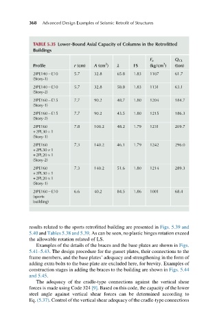
TABLE 5.35 Lower-Bound Axial Capacity of Columns in the Retrofitted
Buildings
F a Q CL
2
2
Profile r (cm) A (cm ) λ FS (kg/cm ) (ton)
2IPE140 E10 5.7 32.8 65.8 1.83 1107 61.7
(Story-1)
2IPE140 E10 5.7 32.8 58.8 1.83 1131 63.1
(Story-2)
2IPE160 E15 7.7 90.2 48.7 1.80 1204 184.7
(Story-1)
2IPE160 E15 7.7 90.2 43.5 1.80 1215 186.3
(Story-2)
2IPE160 7.8 100.2 48.2 1.79 1231 209.7
+2PL30 1
(Story-1)
2IPE160 7.3 140.2 46.1 1.79 1242 296.0
+2PL30 1
+2PL20 1
(Story-2)
2IPE160 7.3 140.2 51.6 1.80 1214 289.3
+2PL30 1
+2PL20 1
(Story-1)
2IPE160 E10 6.6 40.2 84.5 1.86 1001 68.4
(sports
building)
results related to the sports retrofitted building are presented in Figs. 5.39 and
5.40 and Tables 5.38 and 5.39. As can be seen, no plastic hinges rotation exceed
the allowable rotation related of LS.
Examples of the details of the braces and the base plates are shown in Figs.
5.41–5.43. The design procedure for the gusset plates, their connections to the
frame members, and the base plates’ adequacy and strengthening in the form of
adding extra bolts to the base plate are excluded here, for brevity. Examples of
construction stages in adding the braces to the building are shown in Figs. 5.44
and 5.45.
The adequacy of the cradle-type connections against the vertical shear
forces is made using Code 324 [9]. Based on this code, the capacity of the lower
steel angle against vertical shear forces can be determined according to
Eq. (5.37). Control of the vertical shear adequacy of the cradle-type connections