
Page 41 - Advanced Mine Ventilation
P. 41
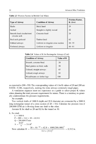
24                                                Advanced Mine Ventilation

         Table 2.3 Friction Factors in British Coal Mines


                                                               Friction Factor,
          Type of Airway          Condition of Airway          K (Ave)
          Shafts                  Brick lined                  29
          Arched                  Straight to slightly waved   28
          Smooth lined circular/semi  Concrete-lined           24
            circular arch
          Steel-arch girdered     Timber-lined                 62
          Unlined airways         Uniform to irregular cross section  20e55
          Timbered airways        Uniform to irregular         48e81


                       Table 2.4 Values of K for Rectangular Airways (Coal)

                        Condition of Airway          Value of K
                        Smooth, concrete-lined        20
                        Steel girders on brick walls  50
                        Unlined, straight airways     65
                        Unlined, rough airways        85
                        Wood beams on timber legs    100


         as expected to 200e350. The corresponding values of l for K values of 20 and 200 are
         0.0246e0.246, respectively, making the mine airways extremely rough pipes.
            A ventilation engineer must use experience as a guide to select proper K values
         when planning the total pressure requirement for mines. There is a tendency to gener-
         ally underestimate the pressure requirements.
            An example:
            Two vertical shafts of 1000 ft depth and 20 ft diameter are connected by a 3000 ft
         long rectangular tunnel of a cross section of 20   8 ft. Calculate the pressure loss if
         200,000 CFM air is flowing from one shaft to the other.
            Assume K for shaft as 20 and K for the tunnel as 30.
         1. For shaft:
              L ¼ 1000 ft
              P ¼ PD ¼ 3.14   20 ¼ 62.8 ft
                         3
              Q ¼ 200,000 ft /min
                  P D 2      2
              A ¼      ¼ 314 ft
                    4
                            20   10  10    62:8   1000ð200; 000Þ 2
            Now calculate H ¼                               ¼ 0:312 in.
                                                3
                                      5:2  ð314Þ