
Page 114 - Advanced Thermodynamics for Engineers, Second Edition
P. 114
5.2 RATIONAL EFFICIENCY 101
(b)
T ' H 1 2
(a)
A
T H
4
T ' L 3s 3
System boundary
C
T ' T 0 D
H W net
E B
T ' L S S δ 12
12
12 12
(c) S S δ 34
34
34
34
T ' 2
H
3
1
T L 3s
T ' L 4 5 6
8 7
δ S
12
12
δ S 34
34
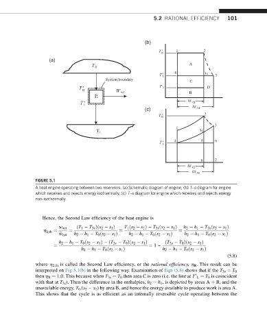
FIGURE 5.1
A heat engine operating between two reservoirs. (a) Schematic diagram of engine, (b) T–s diagram for engine
which receives and rejects energy isothermally, (c) T–s diagram for engine which receives and rejects energy
non-isothermally.
Hence, the Second Law efficiency of the heat engine is
w net ðT 1 T 3s Þðs 2 s 1 Þ T 1 ðs 2 s 1 Þ T 3s ðs 2 s 1 Þ h 2 h 1 T 3s ðs 2 s 1 Þ
h
2;th ¼ ¼ ¼ ¼
b w net h 2 h 1 T 0 ðs 2 s 1 Þ h 2 h 1 T 0 ðs 2 s 1 Þ h 2 h 1 T 0 ðs 2 s 1 Þ
h 2 h 1 T 0 ðs 2 s 1 Þ ðT 3s T 0 Þðs 2 s 1 Þ ðT 3s T 0 Þðs 2 s 1 Þ
¼ ¼ 1
h 2 h 1 T 0 ðs 2 s 1 Þ h 2 h 1 T 0 ðs 2 s 1 Þ
(5.8)
where h 2,th is called the Second Law efficiency, or the rational efficiency, h R . This result can be
interpreted on Fig 5.1(b) in the following way. Examination of Eqn (5.8) shows that if the T 3s ¼ T 0
then h R ¼ 1.0. This because when T 3s ¼ T 0 then area C is zero (i.e. the line at T L ¼ T 0 is coincident
0
with that at T 3s ). Then the difference in the enthalpies, h 2 h 1 , is depicted by areas A þ B, and the
unavailable energy, T 0 (s 2 s 1 ) by area B, and hence the energy available to produce work is area A.
This shows that the cycle is as efficient as an internally reversible cycle operating between the