
Page 40 - Advanced Mine Ventilation
P. 40
Air Flow in Mine Airways 23
2.4 Determination of Mine Airway Friction Factor, K
Because the size and shape of mine airways are greatly variable, they cannot be treated
as pipelines of uniform size and measureable roughness. The friction factor, K, is
hence best obtained by direct measurements.
Many authors have measured the friction factor using models or actual mine air-
ways. These values are listed in different units. They are all modified and expressed
as K in Eq. (2.11) in this book.
2.4.1 Historical Data on Friction Factors for Mine Airways
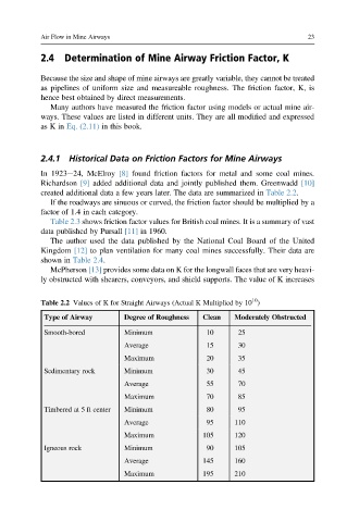
In 1923e24, McElroy [8] found friction factors for metal and some coal mines.
Richardson [9] added additional data and jointly published them. Greenwadd [10]
created additional data a few years later. The data are summarized in Table 2.2.
If the roadways are sinuous or curved, the friction factor should be multiplied by a
factor of 1.4 in each category.
Table 2.3 shows friction factor values for British coal mines. It is a summary of vast
data published by Pursall [11] in 1960.
The author used the data published by the National Coal Board of the United
Kingdom [12] to plan ventilation for many coal mines successfully. Their data are
shown in Table 2.4.
McPherson [13] provides some data on K for the longwall faces that are very heavi-
ly obstructed with shearers, conveyors, and shield supports. The value of K increases
10
Table 2.2 Values of K for Straight Airways (Actual K Multiplied by 10 )
Type of Airway Degree of Roughness Clean Moderately Obstructed
Smooth-bored Minimum 10 25
Average 15 30
Maximum 20 35
Sedimentary rock Minimum 30 45
Average 55 70
Maximum 70 85
Timbered at 5 ft center Minimum 80 95
Average 95 110
Maximum 105 120
Igneous rock Minimum 90 105
Average 145 160
Maximum 195 210