
Page 35 - Aerodynamics for Engineering Students
P. 35
18 Aerodynamics for Engineering Students
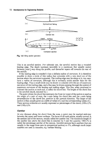
(a 1 Symmetrical fairing
I
(b) Camber line
YU'YS+YC
Y L =ys-yc
(C 1 Cambered aerofoil
Fig. 1.6 Wing section geometry
This is an aerofoil section. For subsonic use, the aerofoil section has a rounded
leading edge. The depth increases smoothly to a maximum that usually occurs
between f and 4 way along the profile, and thereafter tapers off towards the rear of
the section.
If the leading edge is rounded it has a definite radius of curvature. It is therefore
possible to draw a circle of this radius that coincides with a very short arc of the
section where the curvature is greatest. The trailing edge may be sharp or it, too, may
have a radius of curvature, although this is normally much smaller than for the
leading edge. Thus a small circle may be drawn to coincide with the arc of maximum
curvature of the trailing edge, and a line may be drawn passing through the centres of
maximum curvature of the leading and trailing edges. This line, when produced to
intersect the section at each end, is called the chord line. The length of the chord line
is the aerofoil chord, denoted by c.
The point where the chord line intersects the front (or nose) of the section is used as
the origin of a pair of axes, the x-axis being the chord line and the y-axis being
perpendicular to the chord line, positive in the upward direction. The shape of the
section is then usually given as a table of values of x and the corresponding values of y.
These section ordinates are usually expressed as percentages of the chord, (lOOx/c)%
and (lOOy/c)%.
Camber
At any distance along the chord from the nose, a point may be marked mid-way
between the upper and lower surfaces. The locus of all such points, usually curved, is
the median line of the section, usually called the camber line. The maximum height of
the camber line above the chord line is denoted by S and the quantity lOOS/c% is
called the percentage camber of the section. Aerofoil sections have cambers that are
usually in the range from zero (a symmetrical section) to 5%, although much larger
cambers are used in cascades, e.g. turbine blading.