
Page 184 - Air pollution and greenhouse gases from basic concepts to engineering applications for air emission control
P. 184
6.3 Electrostatic Precipitation 159
Δx
d D
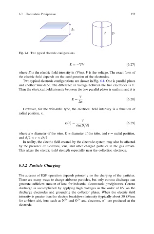
Fig. 6.4 Two typical electrode configurations
E ¼ rV ð6:27Þ
where E is the electric field intensity in (V/m), V is the voltage. The exact form of
the electric field depends on the configuration of the electrodes.
Two typical electrode configurations are shown in Fig. 6.4. One is parallel plates
and another wire-tube. The difference in voltage between the two electrodes is V.
Then the electrical field intensity between the two parallel plates is uniform and it is
V
E ¼ ð6:28Þ
Dx
However, for the wire-tube type, the electrical field intensity is a function of
radial position, r,
V
EðrÞ¼ ð6:29Þ
ð
rln D=dÞ
where d = diameter of the wire, D = diameter of the tube, and r ¼ radial position,
and d=2 \ r \ D=2
In reality, the electric field created by the electrode system may also be affected
by the presence of electrons, ions, and other charged particles in the gas stream.
This alters the electric field strength especially near the collection electrode.
6.3.2 Particle Charging
The success of ESP operation depends primarily on the charging of the particles.
There are many ways to charge airborne particles, but only corona discharge can
generate sufficient amount of ions for industrial electrostatic precipitators. Corona
discharge is accomplished by applying high voltages in the order of kV on the
discharge electrodes and grounding the collector plates. When the electric field
intensity is greater than the electric breakdown intensity (typically about 30 kV/cm
−
for ambient air), ions such as N 2+ and O 2+ and electrons, e , are produced at the
electrode.