
Page 305 - Air pollution and greenhouse gases from basic concepts to engineering applications for air emission control
P. 305
282 10 Post-combustion Air Emission Control
operation allows the gas to enter the filters from the outside surface where the dust
cake builds up. In this case a wire or perforated support structure is needed inside
the filter bags to prevent the filters from being distorted.
Selection of the mode of operation of a filter bag-house depends mainly on the
mechanical properties of the filter medium and the method that is used to remove
the dust cakes on the filters before the critical pressure drop is reached.
10.2.2.3 Dust Cake
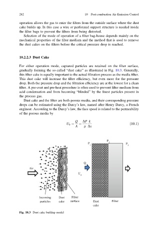
For either operation mode, captured particles are retained on the filter surface,
gradually forming the so-called “dust cake” as illustrated in Fig. 10.3. Generally,
this filter cake is equally important to the actual filtration process as the media filter.
This dust cake will increase the filter efficiency, but even more for the pressure
drop. Both the pressure drop and the filtration efficiency are at the lowest for a clean
filter. A pre-coat and pre-heat procedure is often used to prevent filter medium from
acid condensation and from becoming “blinded” by the finest particles present in
the process gas.
Dust cake and the filter are both porous media, and their corresponding pressure
drops can be estimated using the Darcy’s law, named after Henry Darcy, a French
engineer. According to the Darcy’s law, the face speed is related to the permeability
of the porous media by
Q DP k
U 0 ¼ ¼ ð10:1Þ
A l Dx
P
P 2 P
1 3
Q
Air
U
0
Incoming Dust Filter
particles cake surface Dust Filter
cake
Fig. 10.3 Dust cake buildup model