
Page 156 - Air and Gas Drilling Manual
P. 156
4-42 Air and Gas Drilling Manual
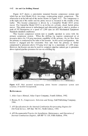
Figure 4-27 shows a semi-trailer mounted booster compressor system unit
which has an Ariel Model JG-4, two-stage, reciprocating piston compressor. The
aftercooler is at the left end of the trailer shown in Figure 4-27. The compressor is
at the right end of the trailer and the prime mover is mounted in the middle of the
trailer. This booster compressor is driven by a Caterpillar Model D353 prime
mover. The Caterpillar Model D353 is an in-line six cylinder, diesel fueled prime
mover. This prime mover is turbocharged and aftercooled and is rated to produce a
peak of 392 horsepower at a speed of 1,200 rpm (at API Mechanical Equipment
Standards standard conditions).
This booster compressor system unit is usually operated in series with the
primary compressor system. When the drilling rig requires compressed air at
pressures above the 310 psig maximum capability of the primary, the air flow from
the primary is conducted to the inlet of the booster. In this series configuration, the
booster is engaged and the volumetric flow rate from the primary is further
compressed to pressures above 310 psig level (up to a maximum of 1,200 psig).
However, the booster can also be used to compress pipeline natural gas to pressures
above typical pipeline pressures for use on a drilling rig.
Figure 4-27: Skid mounted reciprocating piston booster compressor system unit
(courtesy of Symbol Incorporated).
References
1. Atlas Copco Manual, Atlas Copco Company, Fourth Edition, 1982.
2. Brown, R. N., Compressors: Selection and Sizing, Gulf Publishing Company,
1986.
3. API Specification for the Internal-Combustion Reciprocating Engines for
Oil-Field Service, API Std. 7B-11C, Ninth Edition, 1994.
4. API Recommended Practice for Installation, Maintenance, and Operation of
Internal-Combustion Engines, API RP 7C-11F, Fifth Edition, 1994.