
Page 322 - Air and Gas Drilling Manual
P. 322
Chapter 8: Air, Gas, and Unstable Foam Drilling 8-5
For an air or gas drilling operation, this is also the desirable transport situation.
However, the larger the particles being transported the greater the slip velocity of the
particle relative to the gas flow velocity. Further, as the gas volumetric flow rate
decreases, the cutting particles begin to slip in the gas flow transporting them. This
causes the rock cuttings particles to transition from the dilute phase solids flow
condition (where the particles are spread out in the gas) to that of a dense phase
solids flow condition (where the particles are clumped together) (see Figures 8-1 and
8-2). When this occurs, the rock cuttings slow (relative to the gas flow) and the
pressure forcing the gas to flow in the flow line increases. This condition is known
as choking.
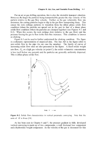
Figure 8-3 can be used to further understand the choking condition. The figure
is a schematic representation of empirical data. The line AB in the figure refers to
zero solids flow in the pipe (in our case the annulus). The family of curves of
increasing solids flow rates are also presented in the figure. A fixed solids weight
˙
rate flow, G , at a high gas velocity (at point C), the solids volumetric concentration
1
is low (well below one percent) and the particles are generally uniformly dispersed.
This is dilute phase solids flow.
Figure 8-3: Solids flow characteristics in vertical pneumatic conveying. Note that the
˙
units of G is lb/sec [10].
As has been seen in Chapter 6 and 7, the pressure gradient in fully developed
vertical conveying is made up of two components, a wall frictional loss component
and a hydrostatic weight component. As the velocity of the gas is decreased for this