
Page 400 - Air and Gas Drilling Manual
P. 400
9-4 Air and Gas Drilling Manual
annulus, the rock cuttings (from the advance of the drill bit) are entrained and the
resulting mixture flows to the surface in the annulus. The mixture exits the annulus
(at P e) into a horizontal flow line. This horizontal flow line flows to either,
conventional open mud tanks, or to sealed returns tanks. Conventional open mud
tanks are used when the returning air is not mixed with contaminated fluids or gases,
or mixed with produced hydrocarbons. Sealed returns tanks are used to contain
contaminated fluids and gases, or hydrocarbons.
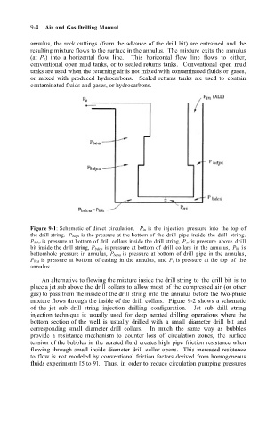
Figure 9-1: Schematic of direct circulation. P in is the injection pressure into the top of
the drill string. P bdpi is the pressure at the bottom of the drill pipe inside the drill string.
P bdci is pressure at bottom of drill collars inside the drill string, P ai is pressure above drill
bit inside the drill string, P bdca is pressure at bottom of drill collars in the annulus, P bh is
bottomhole pressure in annulus, P bdpa is pressure at bottom of drill pipe in the annulus,
P bca is pressure at bottom of casing in the annulus, and P e is pressure at the top of the
annulus.
An alternative to flowing the mixture inside the drill string to the drill bit is to
place a jet sub above the drill collars to allow most of the compressed air (or other
gas) to pass from the inside of the drill string into the annulus before the two-phase
mixture flows through the inside of the drill collars. Figure 9-2 shows a schematic
of the jet sub drill string injection drilling configuration. Jet sub drill string
injection technique is usually used for deep aerated drilling operations where the
bottom section of the well is usually drilled with a small diameter drill bit and
corresponding small diameter drill collars. In much the same way as bubbles
provide a resistance mechanism to counter loss of circulation zones, the surface
tension of the bubbles in the aerated fluid creates high pipe friction resistance when
flowing through small inside diameter drill collar opens. This increased resistance
to flow is not modeled by conventional friction factors derived from homogeneous
fluids experiments [5 to 9]. Thus, in order to reduce circulation pumping pressures