Page 439 - Air and Gas Drilling Manual
P. 439

1 826 6
                                               ,
                                                  .
                                                         .
                                                                       .
                                                                      0 426
                                                              19 47)
                                                ,
                                                         .
                                                       519 67
                                      V
                                                                     &
                                       a3     291 298 %  586 29  (. Chapter 9: Aerated Fluid Drilling    9-43
                                                                   2
                                                          2
                                                               .
                                                      .
                                                  4  0 656    0 375
                                      V a3  247 ft/sec
                                             .
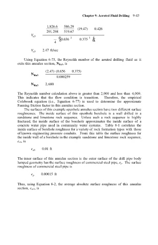
                                   Using Equation 6-75, the Reynolds number of  the  aerated  drilling  fluid  as  it
                               exits this annulus section, N Ra3, is
                                               47
                                              2
                                                   0
                                             (. ) ( .656   . 0 375 )
                                      N  Ra3
                                                    . 0 000259
                                              ,
                                      N  Ra3  2 680
                               The Reynolds number calculation above is  greater than 2,000  and less than  4,000.
                               This  indicates  that  the  flow  condition  is  transition.    Therefore,  the  empirical
                               Colebrook  equation  (i.e.,  Equation  6-77)  is  used  to  determine  the  approximate
                               Fanning friction factor in this annulus section.
                                   The surfaces of this example openhole annulus section have two different surface
                               roughnesses.   The inside  surface  of  this  openhole  borehole  is  a  wall  drilled  in  a
                               sandstone  and  limestone  rock  sequence.    Unless  such  a  rock  sequence  is  highly
                               fractured,  the  inside  surface  of  the  borehole  approximates  the  inside  surface  of  a
                               concrete  water  pipe  used  in  community  water  systems.    Table  8-1  correlates  the
                               inside surface of borehole roughness for a variety of rock formation types with  those
                               of known engineering pressure conduits.   From  this  table the surface roughness for
                               the inside wall of a borehole in the example sandstone and limestone rock sequence,
                               e oh, is
                                      e     001 ft
                                             .
                                       oh
                               The inner surface of this  annulus section is  the outer surface of the drill  pipe body
                               lumped geometry has the surface roughness of commercial steel pipe, e p.  The surface
                               roughness of commercial steel pipe is
                                            .
                                      e p  0 00015 ft
                               Thus,  using  Equation 8-2, the  average  absolute  surface  roughness  of  this  annulus
                               section, e av3, is
   434   435   436   437   438   439   440   441   442   443   444