
Page 76 - Air and gas Drilling Field Guide 3rd Edition
P. 76
4.2 Drill Bits 67
the rock face in compression. This makes the crushing action less efficient and
ultimately reduces the overall drilling rate of the drill bit (for a given WOB).
When this crushing action takes place at the bottom of a well filled only with
compressed air, there is little hydrostatic pressure on the rock face. Further, the
drilling process has removed a column of rock (above the rock face) from a
semi-infinite block of prestressed rock. The in situ preexisting stresses that were
in this block of rock prior to the drilling operation and the vertical cylindrical
void of the new borehole create a thin tension stress field in the rock material just
below the rock (see Figure 4-6).
The aforementioned argument explains why the drilling rate for an air and gas
drilling operation is approximately two to four times greater than that of a similar
mud drilling operation (given similar geology and drilling parameters).
There are four styles of roller cutter drill bits. These are quad-cone drill bits,
tricone drill bits, dual-cone bits, and single cone bits. Quad-cone drill bits and
dual-cone drill bits are used for special mud drilling operations and have little
application in air and gas drilling. Tricone drill bits are used extensively in air
and gas drilling operations.
Tricone Bits
The most widely used roller cutter bit is the tricone drill bit. The tricone drill bit
has three roller cutter cones. Each of these cones has a series of teeth that
crushes rock on the rock face as they roll over the face when the drill string
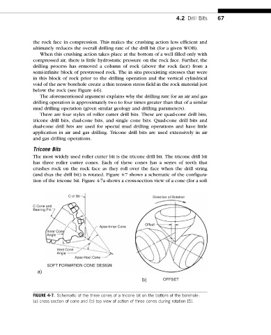
(and thus the drill bit) is rotated. Figure 4-7 shows a schematic of the configura-
tion of the tricone bit. Figure 4-7a shows a cross-section view of a cone (for a soft
C of Bit Direction of Rotation
C Cone and
Bearing Pin
Offset
Apex-Inner Cone
Inner Cone
Angle
Heel Cone
Angle
Apex-Heel Cone
SOFT FORMATION CONE DESIGN
a)
b) OFFSET
FIGURE 4-7. Schematic of the three cones of a tricone bit on the bottom of the borehole:
(a) cross section of cone and (b) top view of action of three cones during rotation [5].