
Page 222 - Aircraft Stuctures for Engineering Student
P. 222
206 Structural instability
-
1.5 rnrn
1.5 rnrn -*
1.5 rnrn
M
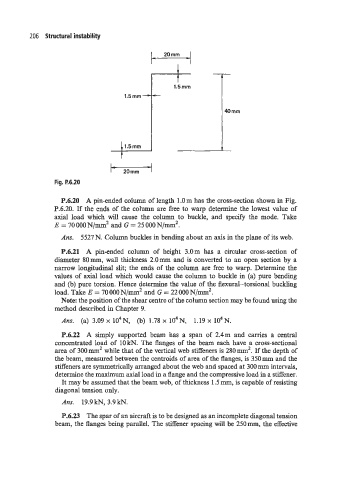
Fig. P.6.20
P.6.20 A pin-ended column of length 1.0m has the cross-section shown in Fig.
P.6.20. If the ends of the column are free to warp determine the lowest value of
axial load which will cause the column to buckle, and specify the mode. Take
E = 70 000 N/mm2 and G = 25 000 N/mm2.
Ans. 5527 N. Column buckles in bending about an axis in the plane of its web.
P.6.21 A pin-ended column of height 3.0m has a circular cross-section of
diameter 80mm, wall thickness 2.0mm and is converted to an open section by a
narrow longitudinal slit; the ends of the column are free to warp. Determine the
values of axial load which would cause the column to buckle in (a) pure bending
and (b) pure torsion. Hence determine the value of the flexural-torsional buckling
load. Take E = 70 000 N/mm'. and G = 22 000 N/mm2.
Note: the position of the shear centre of the column section may be found using the
method described in Chapter 9.
Ans. (a) 3.09 x 10⁴N, (b) 1.78 x 10⁴N, 1.19 x 10⁴N.
P.6.22 A simply supported beam has a span of 2.4m and carries a central
concentrated load of 10 kN. The flanges of the beam each have a cross-sectional
area of 300mm2 while that of the vertical web stiffeners is 280mm'. If the depth of
the beam, measured between the centroids of area of the flanges, is 350 mm and the
stiffeners are symmetrically arranged about the web and spaced at 300 mm intervals,
determine the maximum axial load in a flange and the compressive load in a stiffener.
It may be assumed that the beam web, of thickness 1.5 mm, is capable of resisting
diagonal tension only.
Ans. 19.9 kN, 3.9 kN.
P.6.23 The spar of an aircraft is to be designed as an incomplete diagonal tension
beam, the flanges being parallel. The stiffener spacing will be 250mm, the effective