
Page 43 - Aircraft Stuctures for Engineering Student
P. 43
28 Basic elasticity
Y
Q, (360 x 1 04, ix 650 x 1 04)
(-290 x 1 04,
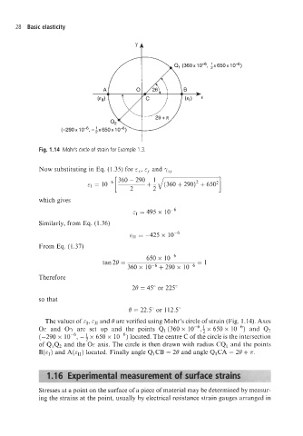
Fig. 1.14 Mohr's circle of strain for Example 1.3.
Now substituting in Eq. (1.35) for E,, E, and -yrY
1
&I = 10- + \/(360 + 290)2 + 6502
which gives
&I = 495 x
Similarly, from Eq. (1.36)
EII = -425 x IOp6
From Eq. (1.37)
650 x
tan20 =
360 x lop6 + 290 x lop6 =
Therefore
20 = 45" or 225"
so that
0 = 22.5" or 112.5"
The values of E~, and 0 are verified using Mohr's circle of strain (Fig. 1.14). Axes
OE and Oy are set up and the points Q1 (360 x lop6,: x 650 x and Q2
(-290 x lop6, - 4 x 650 x IOp6) located. The centre C of the circle is the intersection
of Q1Q2 and the OE axis. The circle is then drawn with radius CQ1 and the points
B(q) and A(eII) located. Finally angle QICB = 20 and angle QICA = 20 + 7r.
Stresses at a point on the surface of a piece of material may be determined by measur-
ing the strains at the point, usually by electrical resistance strain gauges arranged in