
Page 507 - Aircraft Stuctures for Engineering Student
P. 507
488 Structural constraint
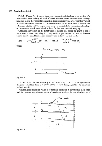
P.11.5 Figure P.11.5 shows the doubly symmetrical idealized cross-section of a
uniform box beam of length 1. Each of the four corner booms has area B and Young’s
modulus E, and they constitute the entire direct stress carrying area. The thin walls all
have the same shear modulus G. The beam transmits a torque T from one end to the
other, and at each end warping is completely suppressed. Between the ends, the shape
of the cross-section is maintained without further restriction of warping.
Obtain an expression for the distribution of the end load along the length of one of
the corner booms. Assuming btl > at2, indicate graphically the relation between
torque direction and tension and compression in the boom end loads.
(CoshpI - 1)
Ans. P = ”” (btl - at2) - sinhpz + sinhpl cosh pz 1
8abGtl t2
where
p2 = 8Gtlt2/BE(at2 + btl)
e
t
t2-4-
Boom area 8
Fig. P.11.5
P.11.6 In the panel shown in Fig. P.11.6 the area, A,, of the central stringer is to be
designed so that the stress in it is 80% of the constant stress, ce, in the edge members,
each of area B.
Assuming that the sheet, which is of constant thickness, t, carries only shear stress
and that transverse strains are prevented, derive expressions for A, and B in terms of
,,SI u n i t length
Fig. P.11.6