
Page 125 -
P. 125
Chapter 3 ■ Digital Morphology 99
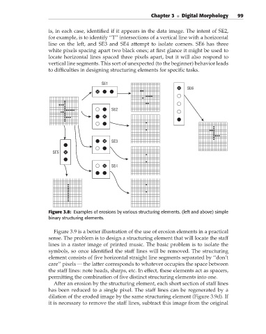
is, in each case, identified if it appears in the data image. The intent of SE2,
for example, is to identify ‘‘T’’ intersections of a vertical line with a horizontal
line on the left, and SE3 and SE4 attempt to isolate corners. SE6 has three
white pixels spacing apart two black ones; at first glance it might be used to
locate horizontal lines spaced three pixels apart, but it will also respond to
vertical line segments. This sort of unexpected (to the beginner) behavior leads
to difficulties in designing structuring elements for specific tasks.
SE1
SE6
SE2
SE3
SE5
SE4
Figure 3.8: Examples of erosions by various structuring elements. (left and above) simple
binary structuring elements.
Figure 3.9 is a better illustration of the use of erosion elements in a practical
sense. The problem is to design a structuring element that will locate the staff
lines in a raster image of printed music. The basic problem is to isolate the
symbols, so once identified the staff lines will be removed. The structuring
element consists of five horizontal straight line segments separated by ‘‘don’t
care’’ pixels — the latter corresponds to whatever occupies the space between
the staff lines: note heads, sharps, etc. In effect, these elements act as spacers,
permitting the combination of five distinct structuring elements into one.
After an erosion by the structuring element, each short section of staff lines
has been reduced to a single pixel. The staff lines can be regenerated by a
dilation of the eroded image by the same structuring element (Figure 3.9d). If
it is necessary to remove the staff lines, subtract this image from the original