
Page 140 -
P. 140
114 Chapter 3 ■ Digital Morphology
// MAX Program to perform a dilation the hard way.
//
int i,j;
image x, y, z;
begin
i :=0;j:=0;
y := !(x<<“$1“); // Allocate a result image like x.
do z<<“$2“; // Read the structuring element.
loop // For all indices i
j:= 0;
loop // For all indices j
if ([i,j] @ x) then // Is pixel i,j in the image?
// Translate structuring element
by i,j
// and OR the result (union)
with y
y := y + (z->[i,j]);
j := j + 1; // Next j
exit when j >= x.cols; // j exceeds maximum column?
end;
i := i + 1; // Next i
exit when i >= y.rows; // i exceeds max row?
end;
do y>>“$3“; // Output the result.
end;
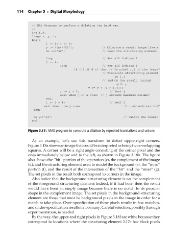
Figure 3.17: MAX program to compute a dilation by repeated translations and unions.
As an example, let’s use this transform to detect upper-right corners.
Figure 3.18a shows an image that could be interpreted as being two overlapping
squares. A corner will be a right angle consisting of the corner pixel and the
ones immediately below and to the left, as shown in Figure 3.18b. The figure
also shows the ‘‘hit’’ portion of the operation (c), the complement of the image
(d), and the structuring element used to model the background (e), the ‘‘miss’’
portion (f), and the result of the intersection of the ‘‘hit’’ and the ‘‘miss’’ (g).
The set pixels in the result both correspond to corners in the image.
Also notice that the background-structuring element is not the complement
of the foreground-structuring element; indeed, if it had been then the result
would have been an empty image because there is no match to its peculiar
shape in the complement image. The set pixels in the background-structuring
element are those that must be background pixels in the image in order for a
match to take place. Over-specification of these pixels results in few matches,
and under-specificationresultsintoomany. Careful selection, possiblythrough
experimentation, is needed.
By the way, the upper and right pixels in Figure 3.18f are white because they
correspond to locations where the structuring element 3.17e has black pixels