
Page 132 - Alternative Energy Systems in Building Design
P. 132
108 SOLAR POWER SYSTEM PHYSICS AND TECHNOLOGIES
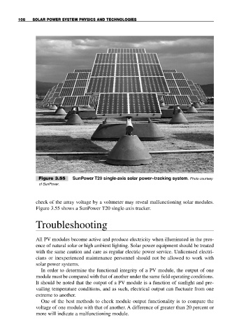
Figure 3.55 SunPower T20 single-axis solar power–tracking system. Photo courtesy
of SunPower.
check of the array voltage by a voltmeter may reveal malfunctioning solar modules.
Figure 3.55 shows a SunPower T20 single-axis tracker.
Troubleshooting
All PV modules become active and produce electricity when illuminated in the pres-
ence of natural solar or high ambient lighting. Solar power equipment should be treated
with the same caution and care as regular electric power service. Unlicensed electri-
cians or inexperienced maintenance personnel should not be allowed to work with
solar power systems.
In order to determine the functional integrity of a PV module, the output of one
module must be compared with that of another under the same field operating conditions.
It should be noted that the output of a PV module is a function of sunlight and pre-
vailing temperature conditions, and as such, electrical output can fluctuate from one
extreme to another.
One of the best methods to check module output functionality is to compare the
voltage of one module with that of another. A difference of greater than 20 percent or
more will indicate a malfunctioning module.