
Page 28 - Amphibionics : Build Your Own Biologically Inspired Robot
P. 28
Amphibionics 01 3/24/03 8:01 AM Page 7
Chapter 1 / Tools, Test Equipment, and Materials
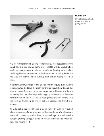
FIGURE 1.9
Wire strippers, cutters,
solder, and a chip-
pulling device.
PIC is reprogrammed during experiments. An adjustable work
stand, like the one shown in Figure 1.10 (M), will be useful when
soldering components to circuit boards, or holding wires when
soldering header connectors to the bare wires. A utility knife (N)
will also be helpful when cutting heat-shrink tubing or small
parts.
A soldering iron, similar to the one shown in Figure 1.11, will be
required when building the main controller circuit boards and the
sensor boards for each robot. An expensive soldering iron is not
necessary, but the advantage to buying a good one is that the tem-
perature can be set. A 15- to 25-watt pencil-style soldering iron
will work and will help to protect delicate components from burn-
ing out.
An adjustable square (O) and a good ruler (P) will be required
when measuring the cutting and drilling marks on the aluminum
pieces that make up each robots’ body and legs. You will need a
hot glue gun (Q) and glue sticks at certain points in the construc-
tion. See Figure 1.12.
7