
Page 276 - Analog and Digital Filter Design
P. 276
Phase-Shift Networks (All-Pass Filters) 2 7 3
Quadrature Networks and Single Sideband Generation
Quadrature networks are filter pairs that produce a 90" phase difference output
when the same signal is applied to each input. This feature has many useful
applications in radio and signal-processing systems. One such application is the
phasing method of single sideband generation, which was developed to provide
generation of a single sideband modulated carrier, without the narrowband
filtering problems. The phasing method will now be described, followed by
a circuit description and analysis of the signal processing that takes place.
When a carrier signal is amplitude modulated it generates two "sidebands"; the
spectrum occupancy is doubled. Suppose a baseband signal occupies the spec-
trum from, say, DC to 4 kHz; after modulating a carrier of 1 MHz it will occupy
frequencies from 1 MHz -4 kHz to 1 MHz + 4 kHz. The reason for the doubling
of spectrum is that the mixer, which produces amplitude modulation, is really
a multiplier. The output in mathematical terms is: cos(o1 .t).cos(w2.tj =
l/2.cos([wl + w21.t) + 1/2.cos([ol - w2].t), where wl is the carrier frequency and
w2 is the information-bearing signal frequency. Amplitude modulation is simple,
but the upper and lower sidebands carry the same information. Removing one
sideband by filtering saves spectrum usage but is difficult, especially at the higher
carrier frequencies.
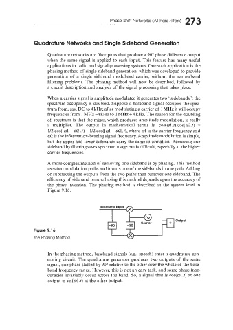
A more complex method of removing one sideband is by phasing. This method
uses two modulation paths and inverts one of the sidebands in one path. Adding
or subtracting the outputs from the two paths then removes one sideband. The
efficiency of sideband removal using this method depends upon the accuracy of
the phase inversion. The phasing method is described at the system level in
Figure 9.16.
Baseband input
I
Figure 9.16
The Phashg Method
In the phasing method, baseband signals (e.g., speech) enter a quadrature gen-
erating circuit. The quadrature generator produces two outputs of the same
signal, one phase shfted by 90" relative to the other over the whole of the base-
band frequency range. However, this is not an easy task, and some phase inac-
curacies invariably occur across the band. So, a signal that is cos(w1.t) at one
output is sin(w1.t) at the other output.