
Page 84 - Analysis and Design of Energy Geostructures
P. 84
54 Analysis and Design of Energy Geostructures
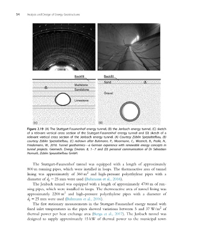
Figure 2.19 (A) The Stuttgart-Fasanenhof energy tunnel, (B) the Jenbach energy tunnel, (C) sketch
of a relevant vertical cross section of the Stuttgart-Fasanenhof energy tunnel and (D) sketch of a
relevant vertical cross section of the Jenbach energy tunnel. (A) Courtesy Züblin Spezialtiefbau, (B)
courtesy Züblin Spezialtiefbau, (C) redrawn after Buhmann, P., Moormann, C., Westrich, B., Pralle, N.,
Friedemann, W., 2016. Tunnel geothermics—a German experience with renewable energy concepts in
tunnel projects. Geomech. Energy Environ. 8, 1 7 and (D) personal communication of Dr Sebastian
Homuth, Züblin Spezialtiefbau GmbH.
The Stuttgart-Fasanenhof tunnel was equipped with a length of approximately
800 m running pipes, which were installed in loops. The thermoactive area of tunnel
2
lining was approximately of 360 m and high-pressure polyethylene pipes with a
diameter of d p 5 25 mm were used (Buhmann et al., 2016).
The Jenbach tunnel was equipped with a length of approximately 4700 m of run-
ning pipes, which were installed in loops. The thermoactive area of tunnel lining was
2
approximately 2200 m and high-pressure polyethylene pipes with a diameter of
d p 5 25 mm were used (Buhmann et al., 2016).
The first stationary measurements in the Stuttgart-Fasanenhof energy tunnel with
2
fixed inlet temperatures in the pipes showed variations between 5 and 37 W/m of
thermal power per heat exchange area (Berga et al., 2017). The Jenbach tunnel was
designed to supply approximately 15 kW of thermal power to the municipal town