
Page 203 - Analysis, Synthesis and Design of Chemical Processes, Third Edition
P. 203
thickness is often required to ensure that the vessel does not buckle under its own weight or when being
transported. In addition to these factors, the costs for the vessel supports, manholes, nozzles, instrument
wells, the vessel head, and so on, all add to the overall weight and cost of the vessel. For the sake of
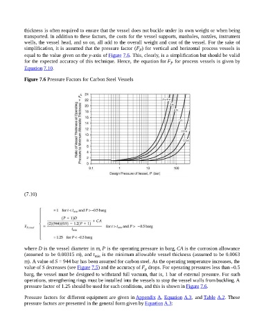
simplification, it is assumed that the pressure factor (F ) for vertical and horizontal process vessels is
P
equal to the value given on the y-axis of Figure 7.6. This, clearly, is a simplification but should be valid
for the expected accuracy of this technique. Hence, the equation for F for process vessels is given by
P
Equation 7.10.
Figure 7.6 Pressure Factors for Carbon Steel Vessels
(7.10)
where D is the vessel diameter in m, P is the operating pressure in barg, CA is the corrosion allowance
(assumed to be 0.00315 m), and t min is the minimum allowable vessel thickness (assumed to be 0.0063
m). A value of S = 944 bar has been assumed for carbon steel. As the operating temperature increases, the
value of S decreases (see Figure 7.5) and the accuracy of F drops. For operating pressures less than –0.5
p
barg, the vessel must be designed to withstand full vacuum, that is, 1 bar of external pressure. For such
operations, strengthening rings must be installed into the vessels to stop the vessel walls from buckling. A
pressure factor of 1.25 should be used for such conditions, and this is shown in Figure 7.6.
Pressure factors for different equipment are given in Appendix A, Equation A.3, and Table A.2. These
pressure factors are presented in the general form given by Equation A.3: