
Page 41 - Antennas for Base Stations in Wireless Communications
P. 41
14 Chapter One
the transmitted power is not that high due to limited battery capacity
and for electromagnetic safety reasons, and thus the PIM reflected to
the receiver is weaker than that at the base station. The relatively low-
power transmission does not reduce the quality of uplink as the base
station is equipped with a highly sensitive receiver. In addition, the
receiver sensitivity is not high at a client terminal, and the reflected
PIM level is thus lower than the noise level. Similarly, the relatively
lower receiver sensitivity does not degrade the downlink performance
as a high-power signal is transmitted from the base station.
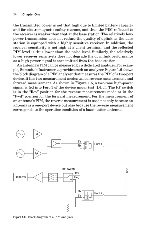
An antenna’s PIM can be measured by a dedicated analyzer. For exam-
ple, Summitek Instruments provides such an analyzer. Figure 1.6 shows
the block diagram of a PIM analyzer that measures the PIM of a two-port
device. It has two measurement modes called reverse measurement and
forward measurement. As shown in Figure 1.6, a two-tone high-power
signal is fed into Port 1 of the device under test (DUT). The RF switch
is in the “Rev” position for the reverse measurement mode or in the
“Fwd” position for the forward measurement. For the measurement of
an antenna’s PIM, the reverse measurement is used not only because an
antenna is a one-port device but also because the reverse measurement
corresponds to the operation condition of a base station antenna.
PA
Tx
Rx Port 1
PA
RF switch DUT
Rev
Receiver Fwd
Rx
Port 2
Tx
Figure 1.6 Block diagram of a PIM analyzer