
Page 62 - Antennas for Base Stations in Wireless Communications
P. 62
Base Station Antennas for Mobile Radio Systems 35
Log field strength Minimum useful
signal
Acceptable level of
interference in neighboring cell
d 1 Log distance d 2
Cell B can
Cell A uses f 1
Re-use distance re-use f 1
3.8
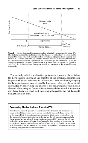
Figure 2.1 Re-use distance. The propagation loss is typically proportional to about d .
The limiting radius of the cell represents the distance at which there is a reasonable
chance the SINR ratio will be sufficient to provide an adequate BER. Beyond this
the use of the same frequency will not be possible because of mutual interference.
At a sufficient distance the signal level has fallen enough for another cell to re-use
the same frequency. The elevation beamwidth of a base station antenna is typically
only 5°–7°. By tilting the beam downward significant reduction of the re-use distance
is possible.
The angle by which the elevation pattern maximum is placed below
the horizontal is known as the beamtilt of the antenna. Beamtilt can
be provided by two mechanisms. Mechanical tilt is provided by angling
the base station antenna physically downward, whereas electrical tilt
is provided by controlling the phases of the radiating currents in each
element of the array so the main beam is moved downward. An antenna
may have both electrical and mechanical beamtilt, the net beamtilt
being the sum of both.
Comparing Mechanical and Electrical Tilt
The effective azimuth pattern of an antenna with electrical tilt diminishes in
range as the tilt increases, but it has an essentially constant shape irrespective
of the applied tilt. If an antenna is mechanically tilted, there is a tendency for
the pattern to become both shorter and wider as the tilt increases, particularly
for antennas having azimuth beamwidths in excess of 60°, because the tilt has
little effect at azimuth angles far from boresight. In a number of situations, for
example an antenna mounted on a wall and firing obliquely from it, an antenna
with mechanical tilt is visually much more obtrusive than an antenna mounted
vertically and provided with electrical tilt.