
Page 158 - Applied Process Design For Chemical And Petrochemical Plants Volume III
P. 158
66131_Ludwig_CH10D 5/30/2001 4:31 PM Page 121
Heat Transfer 121
3 1>4
3k l 1 l v 2 g4
h c 0.728 (10-82)
3 l D o 1T sat T w 24
or
3 1>3
3k l l 1 l v 2gL4
h c 0.951 (10-83)
3 1 W4
where
h c average condensing coefficient on outside of tube,
Btu/(hr) (ft ) (°F)
2
T sat saturation temperature of the vapor, °F
T w wall temperature of tube, °F
L length of tube for heat transfer, ft
W vapor weight (mass) flow rate, lb/hr
D o outside tube diameter, ft
Subscripts:
l liquid
c condensing
v vapor
The preceding equations are reported to predict actual
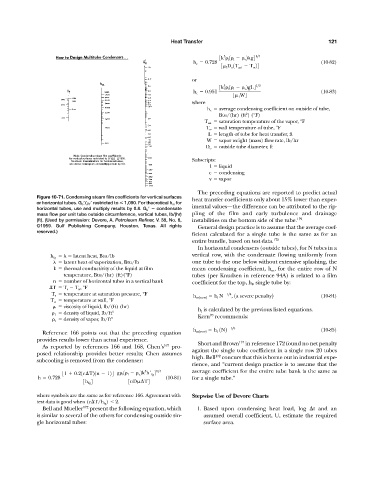
Figure 10-71. Condensing steam film coefficients for vertical surfaces heat transfer coefficients only about 15% lower than exper-
or horizontal tubes. G o / f restricted to 1,090. For theoretical h m for
horizontal tubes, use and multiply results by 0.8. G o condensate imental values—the difference can be attributed to the rip-
mass flow per unit tube outside circumference, vertical tubes, lb/(hr) pling of the film and early turbulence and drainage
(ft). (Used by permission: Devore, A. Petroleum Refiner, V. 38, No. 6, instabilities on the bottom side of the tube. 172
©1959. Gulf Publishing Company, Houston, Texas. All rights General design practice is to assume that the average coef-
reserved.)
ficient calculated for a single tube is the same as for an
entire bundle, based on test data. 172
In horizontal condensers (outside tubes), for N tubes in a
h fg latent heat, Btu/lb vertical row, with the condensate flowing uniformly from
latent heat of vaporization, Btu/lb one tube to the one below without extensive splashing, the
k thermal conductivity of the liquid at film mean condensing coefficient, h m , for the entire row of N
temperature, Btu/(hr) (ft)(°F) tubes (per Knudsen in reference 94A) is related to a film
n number of horizontal tubes in a vertical bank coefficient for the top, h l , single tube by:
T T s T w , °F
T s temperature at saturation pressure, °F h m1new2 h l N 1>4 , 1a severe penalty2 (10-84)
T w temperature at wall, °F
viscosity of liquid, lb/(ft) (hr) h l is calculated by the previous listed equations.
1 density of liquid, lb/ft 3 70
v density of vapor, lb/ft 3 Kern recommends:
h m1row2 h l 1N2 1>6 (10-85)
Reference 166 points out that the preceding equation
provides results lower than actual experience.
Short and Brown 174 in reference 172 found no net penalty
As reported by references 166 and 168, Chen’s 167 pro-
against the single tube coefficient in a single row 20 tubes
posed relationship provides better results; Chen assumes
high. Bell 172 concurs that this is borne out in industrial expe-
subcooling is removed from the condenser:
rience, and “current design practice is to assume that the
3 1>4 average coefficient for the entire tube bank is the same as
31 0.21c T21n 124 g l 1 l v 2k h¿ fg 4
h 0.728 (10-81) for a single tube.”
3h fg 4 3nD T4
where symbols are the same as for reference 166. Agreement with Stepwise Use of Devore Charts
test data is good when (c T/h fg ) 2.
Bell and Mueller 172 present the following equation, which 1. Based upon condensing heat load, log t and an
is similar to several of the others for condensing outside sin- assumed overall coefficient, U, estimate the required
gle horizontal tubes: surface area.