
Page 27 - Applied Process Design For Chemical And Petrochemical Plants Volume III
P. 27
66131_Ludwig_CH10A 5/30/2001 4:07 PM Page 17
Heat Transfer 17
8
Coil*
1
Studs 7
and nuts Manifold
lower*
2 3 4 5 6
Manifold Manifold Base plate Manifold Manifold
nuts lock rings gaskets upper*
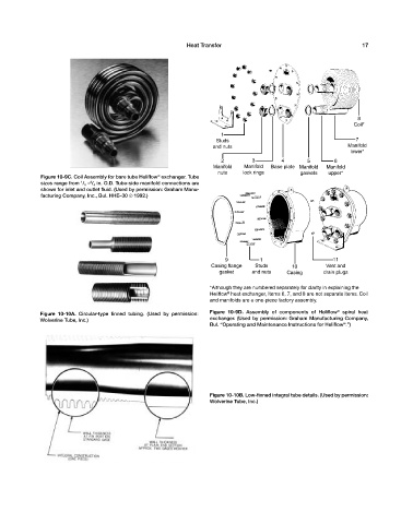
Figure 10-9C. Coil Assembly for bare tube Heliflow exchanger. Tube
®
sizes range from / 4 — / 4 in. O.D. Tube-side manifold connections are
1
3
shown for inlet and outlet fluid. (Used by permission: Graham Manu-
facturing Company, Inc., Bul. HHE–30 © 1992.)
9 1 11
Casing flange Studs 10 Vent and
gasket and nuts Casing drain plugs
*Although they are numbered separately for clarity in explaining the
®
Heliflow heat exchanger, Items 6, 7, and 8 are not separate items. Coil
and manifolds are a one-piece factory assembly.
Figure 10-10A. Circular-type finned tubing. (Used by permission: Figure 10-9D. Assembly of components of Heliflow ® spiral heat
Wolverine Tube, Inc.) exchanger. (Used by permission: Graham Manufacturing Company,
®
Bul. “Operating and Maintenance Instructions for Heliflow .”)
Figure 10-10B. Low-finned integral tube details. (Used by permission:
Wolverine Tube, Inc.)