
Page 190 -
P. 190
158 Part II Gas Drilling Systems
sound in the fluid under the in situ condition, the flow is called a sonic
flow. Under a sonic flow condition, the pressure wave downstream of
the orifice cannot propagate upstream through the orifice because the
medium (fluid) is traveling in the opposite direction at the same or higher
velocity. This causes a pressure discontinuity at the orifice—that is, the
upstream pressure is not influenced by the downstream pressure.
A sonic flow can have many harmful effects on gas drilling operations,
including pipes sticking, ice/hydrate balling of bits, wellbore washouts, and
crooked holes. Because of the pressure discontinuity at the orifice, any
increase in bottomhole pressure due to cuttings accumulation or mud ringing
in the annulus cannot be detected by reading the standpipe pressure gauge.
Cuttings will continue to accumulate until the drill string gets stuck. Often
pipe sticking occurs only a few minutes after a “smooth” drilling operation.
The operation looked smooth because the standpipe pressure was normal,
while the annular pressure had already increased due to cuttings accumulation
or mud ringing. To reduce the possibility of pipe sticking, sonic flow should
be avoided by using larger bit nozzles or orifices in all gas drilling operations.
Whether sonic flow exists at the bit depends on the downstream–
upstream pressure ratio. If this pressure ratio is less than a critical pressure
ratio, sonic flow exists. The critical pressure ratio depends on the fluid
properties, not on the configuration of the orifice. It is expressed as
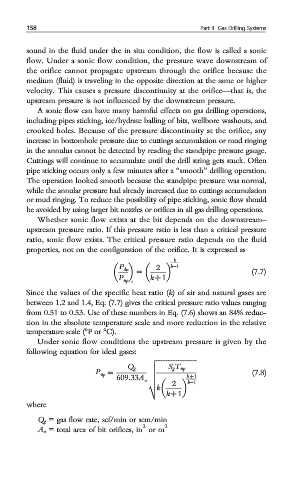
k
k−1
= (7.7)
P dn 2
P up k + 1
c
Since the values of the specific heat ratio (k) of air and natural gases are
between 1.2 and 1.4, Eq. (7.7) gives the critical pressure ratio values ranging
from 0.51 to 0.53. Use of these numbers in Eq. (7.6) shows an 84% reduc-
tion in the absolute temperature scale and more reduction in the relative
temperature scale (°For °C).
Under sonic flow conditions the upstream pressure is given by the
following equation for ideal gases:
v ffiffiffiffiffiffiffiffiffiffiffiffiffiffiffiffiffiffiffiffiffiffiffiffi
u S g T up
Q g
P up = u (7.8)
u k + 1
609:33A o u k−1
2
k
t
k + 1
where
Q g = gas flow rate, scf/min or scm/min
2 2
A o = total area of bit orifices, in or m