
Page 68 -
P. 68
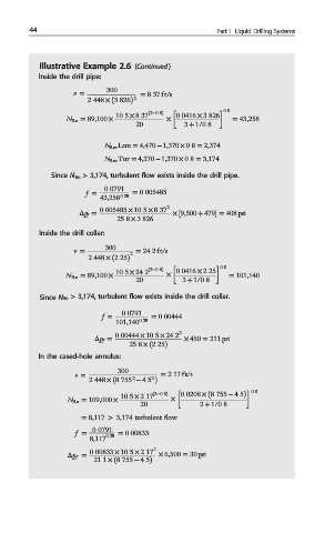
44 Part I Liquid Drilling Systems
Illustrative Example 2.6 (Continued )
Inside the drill pipe:
v = 300 = 8:37 ft/s
2
2:448 × ð3:826Þ
0:8
N Re = 89,100 × 10:5 × 8:37 ð2−0:8Þ × 0:0416 × 3:826 = 43,258
20 3 + 1/0:8
N Rec Lam = 4,470 ‒ 1,370 × 0:8 = 2,374
N Rec Tur = 4,270 ‒ 1,370 × 0:8 = 3,174
Since N Re > 3,174, turbulent flow exists inside the drill pipe.
f = 0:0791 = 0:005485
43,258 0:25
Δp f = 0:005485 × 10:5 × 8:37 2 × ½9,500 + 479 = 408 psi
25:8 × 3:826
Inside the drill collar:
v = 300 = 24:2 ft/s
2
2:448 × ð2:25Þ
0:8
N Re = 89,100 × 10:5 × 24:2 ð2−0:8Þ × 0:0416 × 2:25 = 101,140
20 3 + 1/0:8
Since N Re > 3,174, turbulent flow exists inside the drill collar.
f = 0:0791 = 0:00444
101,140 0:25
Δp f = 0:00444 × 10:5 × 24:2 2 × 450 = 211 psi
25:8 × ð2:25Þ
In the cased-hole annulus:
v = 300 = 2:17 ft/s
2 2
2:448 × ð8:755 − 4:5 Þ
0:8
N Re = 109,000 × 10:5 × 2:17 ð2−0:8Þ × 0:0208 × ð8:755 − 4:5Þ
20 2 + 1/0:8
= 8,117 > 3,174 turbulent flow
f = 0:0791 = 0:00833
8,117 0:25
Δp f = 0:00833 × 10:5 × 2:17 2 × 6,500 = 30 psi
21:1 × ð8:755 − 4:5Þ